Even if you can calibrate or tune to minimise negative effects, it still remains that the slicer puts the inner and outer wall starts in different places for no discernable reason, resulting in an unnecessary retract + substantial move + restart instead of a 0.5mm no-retract travel, resulting in more potential for surface finish defects. I've seen this before too but at the time I had reached my limit for the day of dumb slicer problems to bother with troubleshooting and making test prints.
Re: Starting position
Ah finally someone experienced the same 😉
Hmm...maybe I could try with an older version of PS or use Slic3r in certain cases....
with Micro Swiss Direct Drive, BTT SKR v1.3 and TMC2208<br>Ender-3 with Micro Swiss Direct Drive, E3 mini with TMC2208<br>Qidi i-Mate S
Perimeter seams are weak points
I just wanted to mention that for mechanically stressed parts it is an serious disadvantage, if the slicer lines up the start points of the external and internal perimeters.
I thought about making a github suggestion that there should be a setting to tell the slicer to make a certain offset between the start points of internal and external perimeters. The part would be mechanically stronger.
Re: Perimeter seams are weak points
Hmm...something totally new to me.....
But I learned so much today in this thread...even as an old mid 50s electronic guy started with vacuum tubes 😉
PS: Still a great and my favourite slicer.....and even a awesome community help here 🙂
with Micro Swiss Direct Drive, BTT SKR v1.3 and TMC2208<br>Ender-3 with Micro Swiss Direct Drive, E3 mini with TMC2208<br>Qidi i-Mate S
And so what?
[...] resulting in an unnecessary retract + substantial move + restart instead of a 0.5mm no-retract travel, resulting in more potential for surface finish defects.
If the perimeters are part of the same wall and the moves remain inside, who cares? Or are we worried about the possibility of stringing inside the part hat will be entombed in plastic forever?
This seems to be a lot of worry over something that doesn't cause actual problems in real life. I only retract when crossing perimeters when it matters.
@bobstro
This seems to be a lot of worry over something that doesn't cause actual problems in real life. I only retract when crossing perimeters when it matters.
Wiser words have not been spoken. I still haven't seen a single picture showing any meaningful defects caused by this. I've actually looked at the tool paths in some examples, including the benchy and the 3mf file the OP uploaded, and in most cases the starts of inner and outer perimeters look closely aligned. If you just load a simple shape (such as a box), the inner and outer perimeter starts are actually very close together, but not identical, and I had the same thought as @stefan-3 that absolutely aligning them would actually create weaknesses in the model. So I don't know...in the absence of evidence to the contrary, I consider this a somewhat abstract discussion and a practical non-issue.
The seam being placed in different locations on the inner and outer wall can be triggered by painting the seam. In the following picture, the upper piece has inner and outer seams aligned whereas the lower piece has them separated. This wall is printed from left to right, so the start of the line is on the right side of the seam and the end, after it has looped around the back, is on the left.
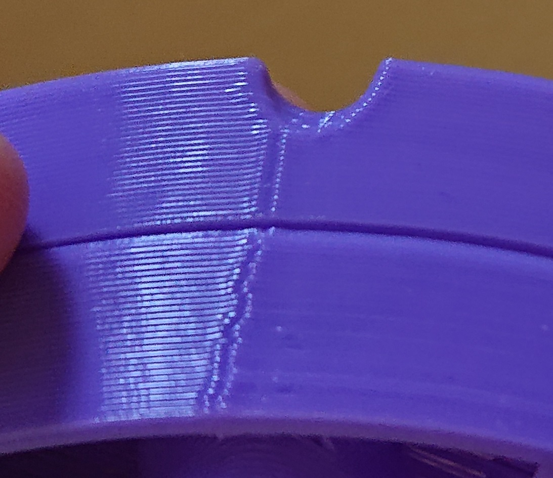
In the image above, the lower piece has larger blobs at the beginning (right) side of the seam compared to the upper piece.
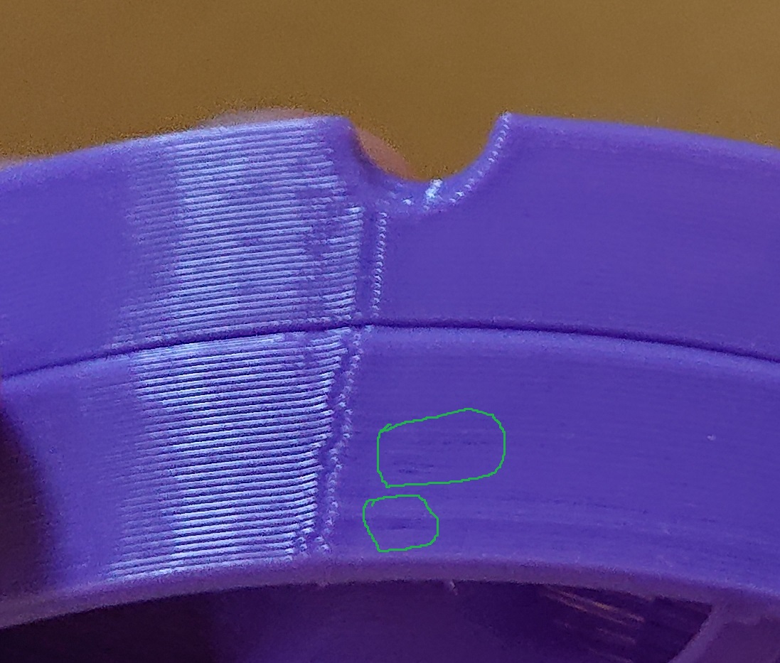
The lower piece also has small extrusion defects close to the restart, whereas the upper piece is completely clean.
In the last picture below (you may have to click the image), the two pieces are reversed so that the aligned seam print is on the bottom.
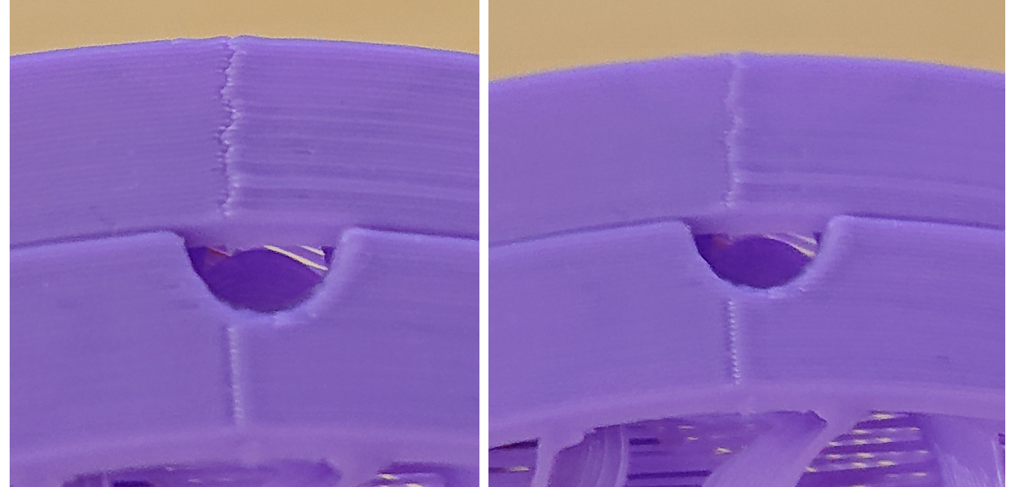
In the left shot, the rear piece is in better focus, while in the right shot, the front piece is in better focus. Again, the seam with inner and outer wall seams aligned is less prominent. You can also see a banding effect on the separated seam piece, because after a restart the extrusion is not as stable as normal. There's patents (e.g. 8349239) about hiding the extrusion immediately after a restart, so it's not contentious that the quality is worse.
Also if lining up the seams is bad for strength, that would mean having control over whether the seams are aligned or separated is even more important. See also same issue https://github.com/prusa3d/PrusaSlicer/issues/4924 , also I remember reading an issue where someone wanted more well separated "random" seam to help make things watertight, but I can't find it.
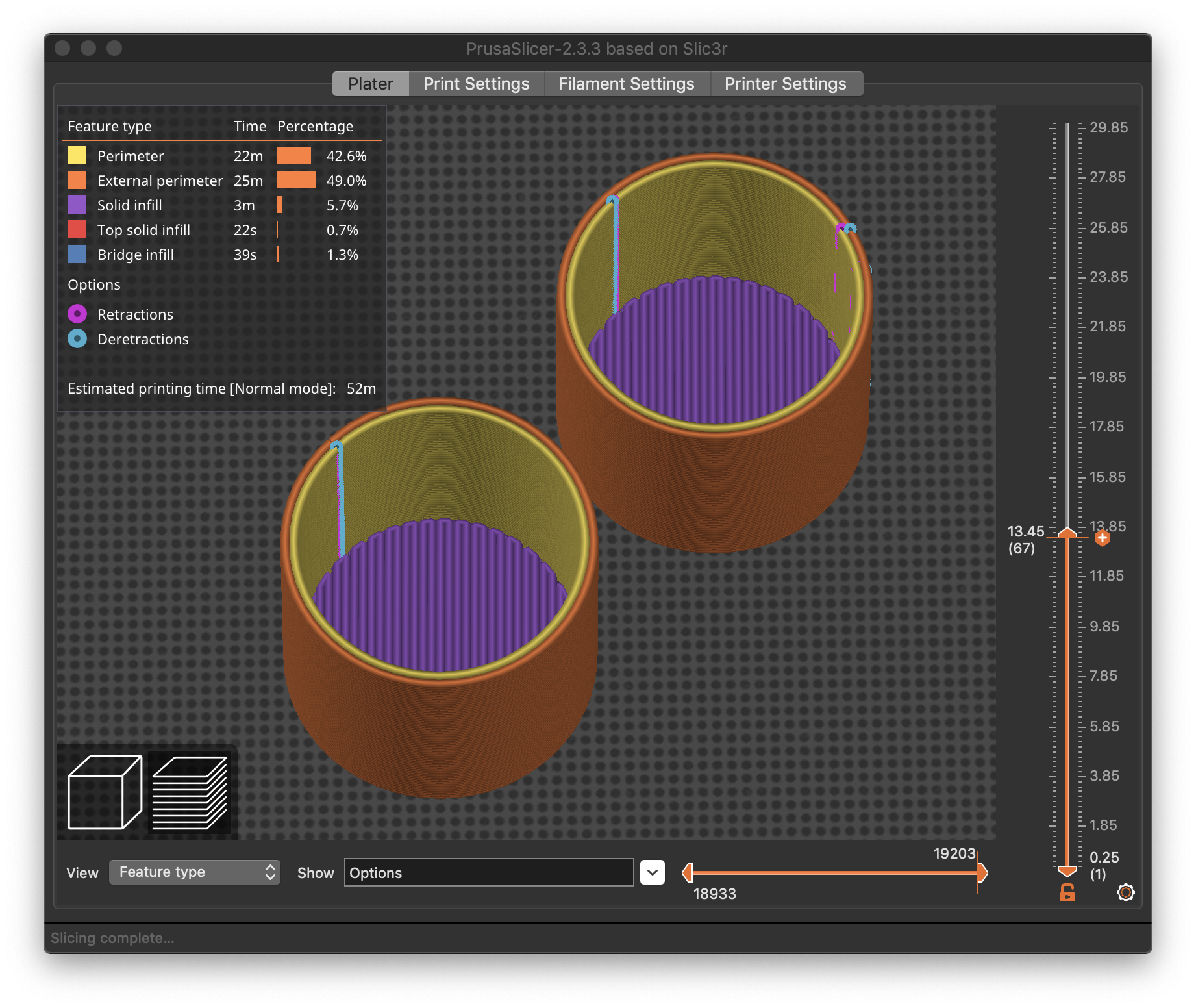
You can force inner and outer seam position using Rear placement
If you are really concerned about the placement of seams in locations that will not be visible in the final print, you can use the Rear alignment option. This tries (but cannot always) place all seams aligned to the rear of the bed. The part at lower-left has been set to use a manual rear-aligned z-seam placement.
If you read the Prusa knowledgebase article carefully, they state that the algorithm tries to honor the placement option while still having to consider other factors and will always try to use a non-overhang corner if available. So far as the other wall blemishes, these can also occur around any feature (hole, window) that requires a restart. As the article states:
With the FFF/FDM technology, it is not possible to entirely eliminate the seam. It will always be somewhat visible. However, with well-tuned settings, it shouldn't be too noticeable.
Settings that affect the visibility of the seam are Linear Advance and Extrusion multiplier calibration. Original Prusa profiles have these settings already tuned, but if you're fine-tuning a custom profile, you can try lowering the extrusion multiplier and calibrating the linear advance value to lower the visibility of the seam.
The gap defects can occur independently of the seam placement. The placement of the seam in some locations triggers the problem, but that's not the root cause of the problem. If you're getting bulges or gaps in your z seam, LA, acceleration/jerk, and over/under extrusion are likely the cause. The seam will never be perfect, but you can certainly minimize it. If you have either problem, aligning inner and outer perimeters exactly is likely to make the problem worse.
Michael Hackney has an excellent discussion on this topic, unfortunately using the (apparently) defunct KISSlicer. KISS had some great features for fuzzing the z-seam location that would be nice to see in PrusaSlicer.
Feature requests versus bugs
I'm all for making more feature requests, and many have been made. If you read through many of those thousands of entries on GitHub (open and close), you'll see that they tend to fizzle out with a discussion on the importance of linear advance, acceleration/jerk settings, and extrusion multipliers. While a feature is nice, I don't consider this a damning defect in PrusaSlicer.
Re: Feature requests versus bugs
Sorry being absent for a while.....and thanks for all the great feedback 🙂
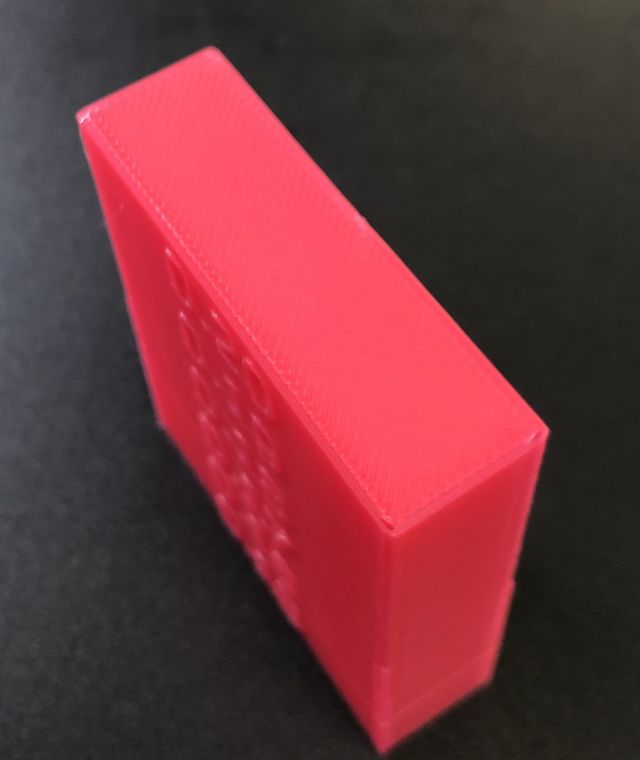
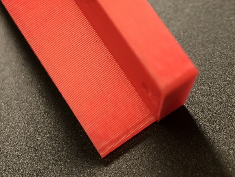
Hmm..IIRC someone wanted me to post a picture..not the best camera it is...but hopefully the slight underextrusion is visible. The outer wall start here in the corner when the layer height was above the screw hole at the right...

Linear advance is really some new material to me....but might be as not many are using it on Marlin-2.x with Trinamic chips. And I probably know why....
Had to replace the TMC2208 with a TMC2209 for the extruder to make LA work, otherwise extruder stops completely when k > 0.
The test pattern was printed okay..and I could notice some differences when going from K = 0.0 to K = 0.1, though not much...but what really is annoying now is the ratteling noise of the extruder when doing infills where it acc/decelerates a lot...not sure if that's how it should be...or if LA is completely useless when using Trinamic (either stealth or spread cycle mode).
Guess I need some more test pattern and cube prints..maybe with a non-shiny filament...or just leave LA to the professional people here 😉
with Micro Swiss Direct Drive, BTT SKR v1.3 and TMC2208<br>Ender-3 with Micro Swiss Direct Drive, E3 mini with TMC2208<br>Qidi i-Mate S
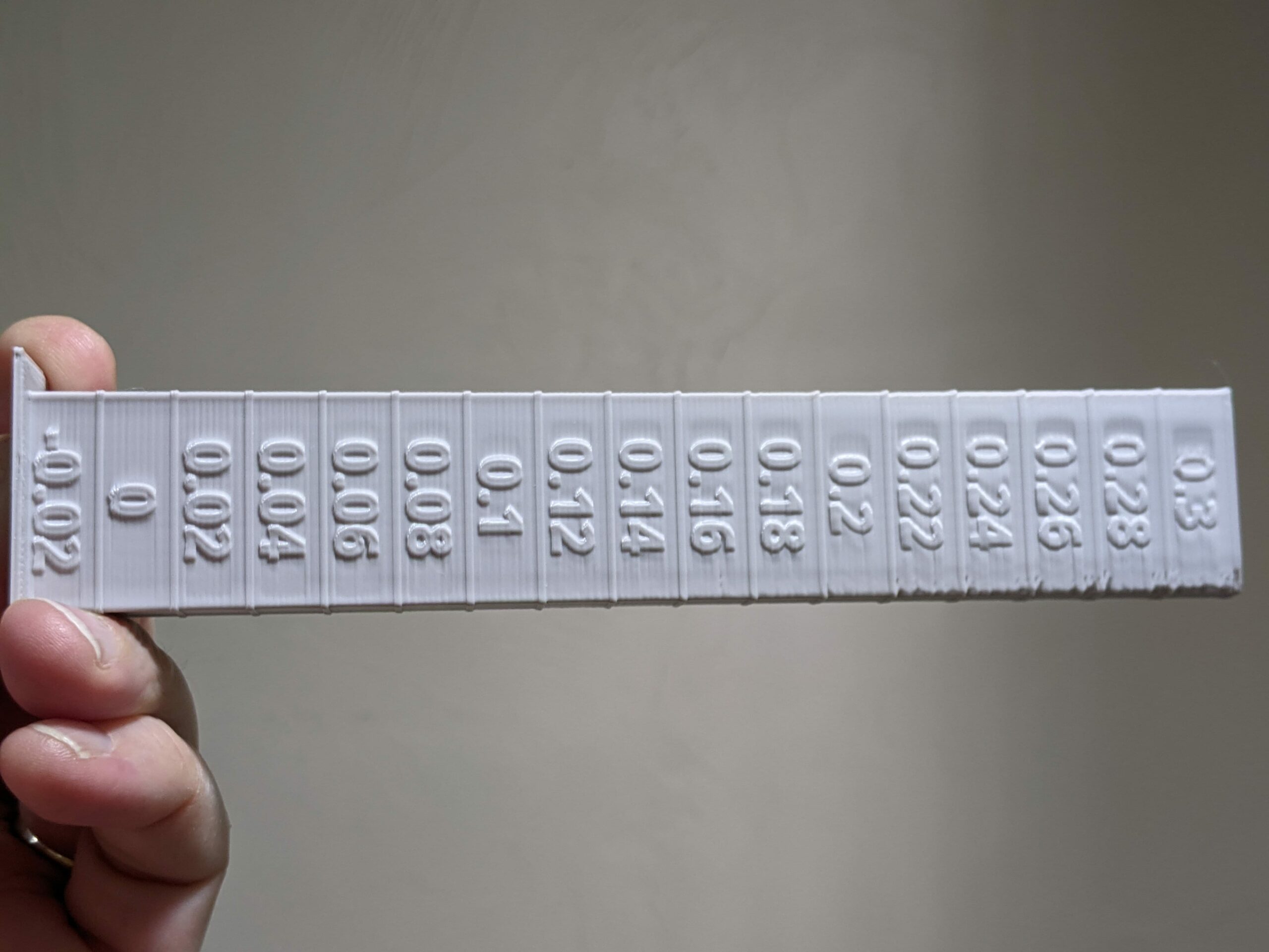
LA 1.5 values are -0.02 to 2.0
LA1.5 values for a direct drive extruder are usually in the range -0.02 to 2.0. Try testing in increments of 0.02. Here's a test print showing the results at different values.
LA test print
Good morning
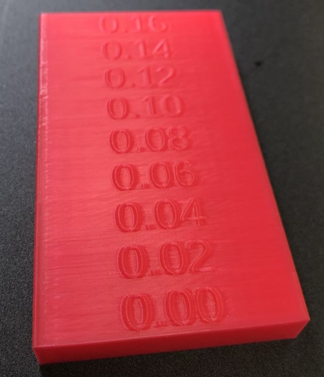
Did a OpenSCAD LA tower....and the changes per K value look different....for example with K_0.10 it looks better than 0.08 or 0.12.
The best spot seems around 0.18 for my PLA:
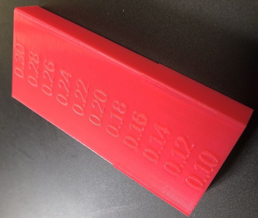

What puzzles me is the huge difference between 0.16 and 0.18....and still don't know why the extruder sounds like a horse galloping at specific K values.
with Micro Swiss Direct Drive, BTT SKR v1.3 and TMC2208<br>Ender-3 with Micro Swiss Direct Drive, E3 mini with TMC2208<br>Qidi i-Mate S
Check ranges?
[...] What puzzles me is the huge difference between 0.16 and 0.18
That is a sudden change in quality. Seriously, check your gcode. I managed to screw up the M900 syntax a couple of times and shift the decimal point when figuring out my towers. And @ringarn67 still managed to find errors in my notes page.
....and still don't know why the extruder sounds like a horse galloping at specific K values.
It may be something Creality specific. Does it should like the extruder skipping (rapid fire loud clicking)? I've had that happen at the higher values.
GCode is fine
Always looked at the GCode before printing...and it looks okay with M900 K0.16.
Turned down Jerk for XY to 7mm7sec but it is still rattling like mad at 0.16 and under extruded one outer perimeter, at 0.17 only rattling at the fine text details.....
Maybe difficult to describe the noise as a non-native English speaker, so I uploaded a video showing K at 0.15 and 0.16:
Might be that the Marlin LA code with the TMC drivers creates at specific values some stepper harmonics...
At least at those K values the rattling is present:
K = 0.02
K = 0.04
K = 0.08
K = 0.11
K = 0.16
K = 0.17
Printing a new LA tower now from 0.15 to 0.20 in 0.01 steps....
with Micro Swiss Direct Drive, BTT SKR v1.3 and TMC2208<br>Ender-3 with Micro Swiss Direct Drive, E3 mini with TMC2208<br>Qidi i-Mate S
Tower printing finished
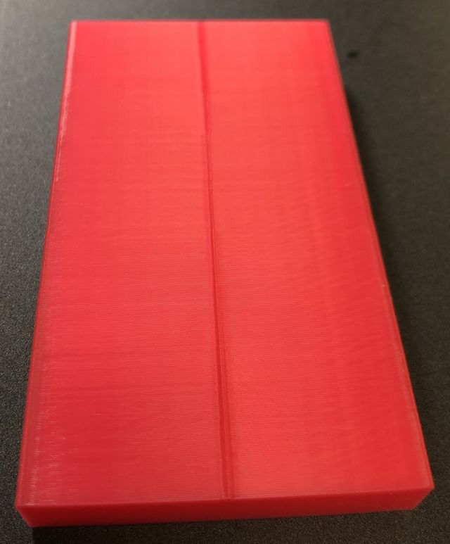
This is now the LA tower finished as shown in the Youtibe video link above:
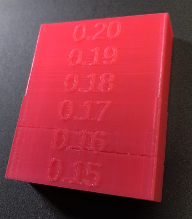
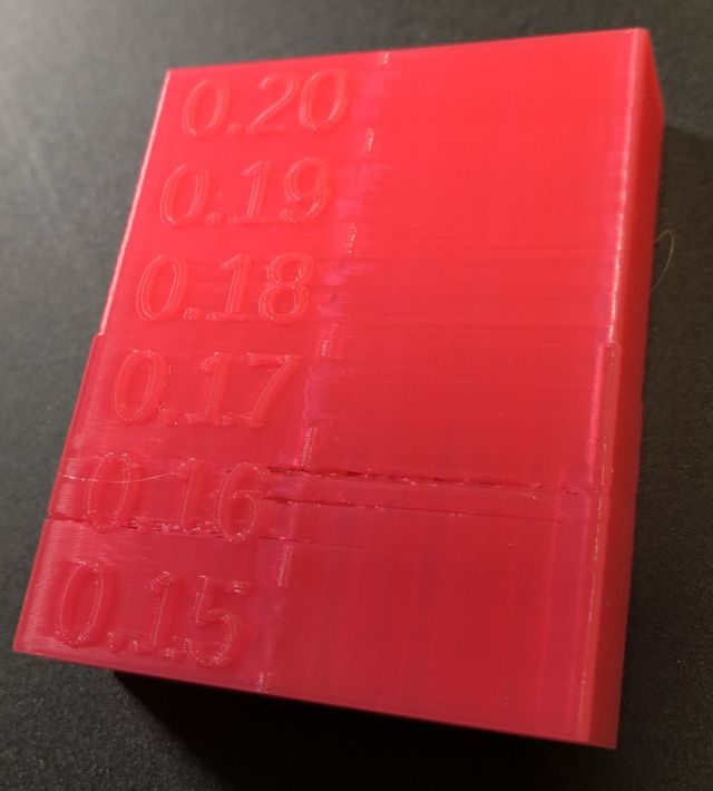
The rattling at K = 0.16 caused this time an under extrusion at several outer perimeters....
Result is similar from previous prints...looks that the sweet spot is around K = 0.19/0.20.
Looks I have to talk to some Marlin guys about the rattling issues..I still believe it is caused by miscalculation/overflows at specific values or I should try with a much faster board than the LPC1768 and/or other stepper driver for the extruder than the TMC2209.
BTW: What CPU/stepper driver are you using?
with Micro Swiss Direct Drive, BTT SKR v1.3 and TMC2208<br>Ender-3 with Micro Swiss Direct Drive, E3 mini with TMC2208<br>Qidi i-Mate S
If you are really concerned about the placement of seams in locations that will not be visible in the final print, you can use the Rear alignment option. This tries (but cannot always) place all seams aligned to the rear of the bed. The part at lower-left has been set to use a manual rear-aligned z-seam placement.
The problem has nothing to do with the placement of the inner seam except for it being separate to the outer seam, causing a restart. I'm not sure why you keep implying that people care about the inner seam location by itself.
If you read the Prusa knowledgebase article carefully, they state that the algorithm tries to honor the placement option while still having to consider other factors and will always try to use a non-overhang corner if available. So far as the other wall blemishes, these can also occur around any feature (hole, window) that requires a restart. As the article states:
With the FFF/FDM technology, it is not possible to entirely eliminate the seam. It will always be somewhat visible. However, with well-tuned settings, it shouldn't be too noticeable.
Settings that affect the visibility of the seam are Linear Advance and Extrusion multiplier calibration. Original Prusa profiles have these settings already tuned, but if you're fine-tuning a custom profile, you can try lowering the extrusion multiplier and calibrating the linear advance value to lower the visibility of the seam.
The gap defects can occur independently of the seam placement. The placement of the seam in some locations triggers the problem, but that's not the root cause of the problem. If you're getting bulges or gaps in your z seam, LA, acceleration/jerk, and over/under extrusion are likely the cause. The seam will never be perfect, but you can certainly minimize it. If you have either problem, aligning inner and outer perimeters exactly is likely to make the problem worse.
It is not always possible to completely tune out all triggered defects. Optimising the print path to avoid unnecessarily triggering defects is just as important as tuning. That's why people patent seam hiding techniques. Go tell stratasys they should have just tuned their LA instead.
Big theories are nice, but let's focus on helping the user with a problem
[...] It is not always possible to completely tune out all triggered defects. Optimising the print path to avoid unnecessarily triggering defects is just as important as tuning. That's why people patent seam hiding techniques. Go tell stratasys they should have just tuned their LA instead.
Most everybody in this thread is trying to help @davorin troubleshoot problems. You have chimed in with your opinions on what you deem the correct solution. While those are possibly of interest to some readers, the suggestion to tune LA and other steps have been made to aid @davorin in resolving a problem, not as some theoretical exercise in measuring small parts.
LA is now PA (o;
Good morning
Did some more testing over the last weekend...and since I couldn't get Marlin to do proper LA I decided to dump it completely for Klipper and its PA feature (o;
The transition between incrementing PA values is now much more smoother..and what it's best of all:
Absolutely no extruder rattling anymore 🙂
For the seam position I have to use more the preview feature and watch how the tool path is chosen...definitively worth to spend few minutes there and maybe make some changes to slicer settings before starting a long print (o;
Gonna stick with Prusa Slicer anyway 🙂
Many thanks again for so many hints, suggestions and pointer 😉
with Micro Swiss Direct Drive, BTT SKR v1.3 and TMC2208<br>Ender-3 with Micro Swiss Direct Drive, E3 mini with TMC2208<br>Qidi i-Mate S
That's one solution!
Did some more testing over the last weekend...and since I couldn't get Marlin to do proper LA I decided to dump it completely for Klipper and its PA feature (o;
Well, you woke up ambitious! I've heard good things about klipper. Sounds like it worked well in this situation. Good job, and congrats!
The transition between incrementing PA values is now much more smoother..and what it's best of all:
Absolutely no extruder rattling anymore 🙂
Klipper has an alternative to Linear Advance, I believe. Can't recall what it's called right now. Are you using that?
For the seam position I have to use more the preview feature and watch how the tool path is chosen...definitively worth to spend few minutes there and maybe make some changes to slicer settings before starting a long print (o;
So have you worked past the original problem at this point? Anything still not working?
I am happy now (o;
Just did another test print I had problems with where start of inner and outer wall were far apart....
Tried with different slicer settings where the start of both are closer together...inner wall starts at the right back corner..and the outer wall at the hole nearby:
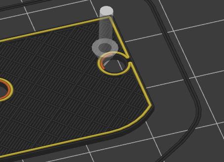
Don't see any under extrusion there anymore (o;
Overall I am very happy now with the result that Prusa Slicer together with Klipper and PA produces now:

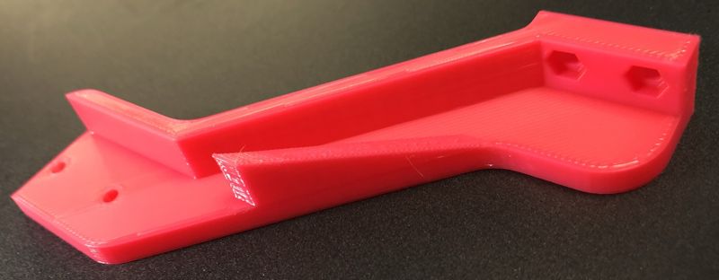
Case closed 😉
with Micro Swiss Direct Drive, BTT SKR v1.3 and TMC2208<br>Ender-3 with Micro Swiss Direct Drive, E3 mini with TMC2208<br>Qidi i-Mate S