Limit bed boundaries of movements.
Hello.
Wanted to know if there is a way to limit bed boundaries of movements.
I've build closure V2 and and there is lack of space in Y axis.
I didn't change cable connector to the bed to 60 degree, have a problem with it.
The LCD mount I changed to be short.
Only after any printing job finished , the bed comes forward on me and hits and opens the doors of the closure.
How can I change/limit bed area movement in software or options of the printer ?
I know I limit maximal printing area , but it almost unused border, never used models which need full YX space.
RE: Limit bed boundaries of movements.
In the slicer: Printer settings > General > Bed shape. You might also need to set Printer settings > Extruder 1 > Offset, to center the printing on the newly defined bed shape.
Mk3S+,SL1S
RE: Limit bed boundaries of movements.
I changed y-size from 210 to 200, in order the bed does not move out to the end. I hope it will work not as printing area , also when a job finished and bed goes out.
Why need I add an offset to the extruder ?

RE: Limit bed boundaries of movements.
Now that I think on it more, I don't think you need to do an offset. Try it without and see.
Mk3S+,SL1S
RE: Limit bed boundaries of movements.
When printing job finish , the bed still goes out to the end...
RE: Limit bed boundaries of movements.
You could try changing end-of-print g-code from the slicer: Printer Settings > Custom G-code. You will see a chunk of code in the second box down labeled 'End G-code.' Find the second to last line which says: G1 X0 Y200 F3000 ; home X axis
and delete this line of code.
Mk3S+,SL1S
RE: Limit bed boundaries of movements.
You could try changing end-of-print g-code from the slicer: Printer Settings > Custom G-code. You will see a chunk of code in the second box down labeled 'End G-code.' Find the second to last line which says: G1 X0 Y200 F3000 ; home X axis
and delete this line of code.
Thank you,
According to Prusa G-code Viewer the bed will stop above a model.
Also , can I change bed calibration points ? Before each printing , there is bed calibration and the far points (end of the bed) cause the bed hit the doors of the closure (not hitting hard, but still).
RE: Limit bed boundaries of movements.
My research shows that this can only be done by making changes in the firmware. I have no experience in making changes in the firmware so I wouldn't try to advise you. Perhaps someone else will have a better answer.
Mk3S+,SL1S
RE: Limit bed boundaries of movements.
If the original poster is using a prusa then you cant change the calibration points in firmware either. They are positioned to cover the bed but also to avoid the magnets holding the print sheet down. I mean you *could* in the firmware but I wouldn't expect the readings from the pinda probe to be correct.
For all this trouble why not just print out the alternate cable cover so that your printer actually fits in the enclosure ? Or modify the back of the enclosure to make it an inch or so bigger. Seems like you are making things difficult for yourself.
RE:
If the original poster is using a prusa then you cant change the calibration points in firmware either. They are positioned to cover the bed but also to avoid the magnets holding the print sheet down. I mean you *could* in the firmware but I wouldn't expect the readings from the pinda probe to be correct.
For all this trouble why not just print out the alternate cable cover so that your printer actually fits in the enclosure ? Or modify the back of the enclosure to make it an inch or so bigger. Seems like you are making things difficult for yourself.
Cable cover of 60 degree causes to collision between cables of the bed and of the hotend.
And it is too much big effort to modify the the back .
And I don't want to cancel the calibration points, just to move it 0.5 centimeter.
RE: Limit bed boundaries of movements.
Is the only issue now the mesh bed leveling? Why not just leave the door open at the start of the print until the leveling has completed?
Mk3S+,SL1S
RE: Limit bed boundaries of movements.
I have the 60 degree cover and I don't get collisions between the cables. Most people don't. So all I can surmise is that the twist on the sleeve or the angle they are clamped in on the einsy case could be off. Its certainly possible to assemble it all without that difficulty. Hundreds of people have built the enclosure and have it printing successfully.
I get that you want to move the points and not cancel them, however that's just the potential problem as moving them could cause faulty pinda probe readings.
Still think you are going the difficult route. Re-assessing the printer build to stop the cable clash is the easiest option. Moving the back out is next easiest as it is a few hour job, including designing and printing some spacers versus hours to days of fiddling with firmware, that's once you have spent hours actually setting up the build environment to compile it which by all accounts is not easy. But hey, if you like doing things that way its up to you. Good luck.
RE: Limit bed boundaries of movements.
Is the only issue now the mesh bed leveling? Why not just leave the door open at the start of the print until the leveling has completed?
It what I do now, but sometimes forgot.
RE: Limit bed boundaries of movements.
I have the 60 degree cover and I don't get collisions between the cables. Most people don't. So all I can surmise is that the twist on the sleeve or the angle they are clamped in on the einsy case could be off. Its certainly possible to assemble it all without that difficulty. Hundreds of people have built the enclosure and have it printing successfully.
I get that you want to move the points and not cancel them, however that's just the potential problem as moving them could cause faulty pinda probe readings.
Still think you are going the difficult route. Re-assessing the printer build to stop the cable clash is the easiest option. Moving the back out is next easiest as it is a few hour job, including designing and printing some spacers versus hours to days of fiddling with firmware, that's once you have spent hours actually setting up the build environment to compile it which by all accounts is not easy. But hey, if you like doing things that way its up to you. Good luck.
The cable of the bed as is goes parallel and below the hotend cable.
I try to set the corner 60 deg, but the bed cable collisions with hotend cable.
Can you take a picture how it looks on your printer please ?
RE: Limit bed boundaries of movements.
Your heat bed cable appears to be at 90 degrees, not 60 from your picture.
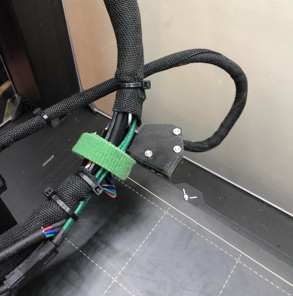
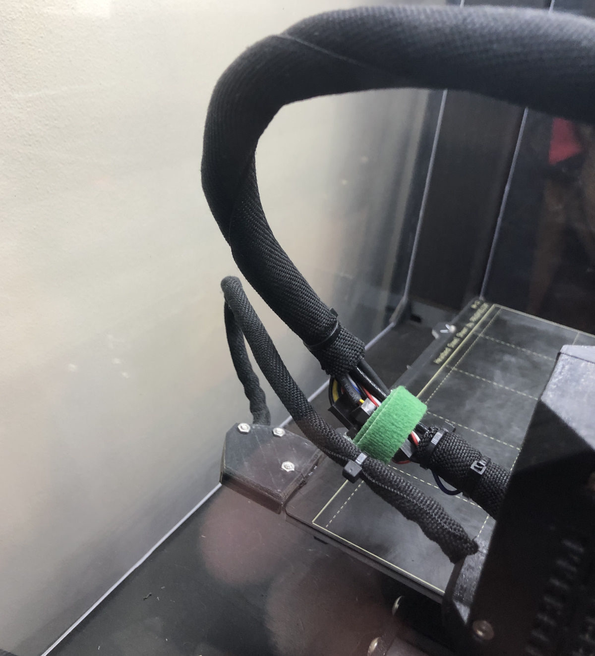
Here is the cable exiting at 60 degrees. When its fully back its about 1mm off the plexi rear sheet. As it moves forward it lowers down and slips under the x axis bundle. Even with the extra velcro strapping I have on my bundle.
If you are wondering why the X axis bundle looks different, its because I fitted connectors to almost all the cables. I can swap out both fans, my thermistor and the heater cartridge without taking it all apart. Even with that extra bulk there is no touching of the cables.
I also recall seeing on thingiverse a different printed part for the bed cables that exited at 90 degrees sideways rather than back. I almost printed one out but as the one fitted has been working fine for over 3 years I didn't bother.
Looking at my own pics it looks like I'm about due a good print sheet cleaning, I can see a thumb print in the back left corner where I've been flexing it 🙂