Any way to disable separation of "exterior" or bridge portion of layer from the rest of the layer when the whole layer is solid?
I want, and expect, 1 solid layer to print but it always slices with exterior or bridge parts of the layer separate from the rest of the layer when it would print 110x better (smoother, better bridge, and better adhesion of bridging over infill) if it was printed as a single solid layer vs the separation. Cura doesn't do this and I can't find any way to stop it in PrusaSlicer. I hate doing multicolor prints in Cura and this is the only behavior that forces me to use it due to the awful way prints turn out when it does this. Is there anything I can do outside of making the object thicker and adding more solid layers to mitigate this making prints look like trash?


Re: Any way to disable separation of "exterior" or bridge portion of layer from the rest of the layer when the whole layer is solid?
I've been looking for the same thing, but I haven't found it. If only there had been a function to disable bridging, or at least some workaround to effectively disable it, I'd have been much happier.
I'm trying to move away from the (now dead) S3D, but small things like this is making it more difficult. In S3D I can simply just increase the "Unsupported area threshold" to a large value, and it slices without trying to do any bridging.
Save your project, rename the resultant .3MF fir as .ZIP and post it?
Save your project, rename the resultant .3MF fir as .ZIP and post it?
Please dont rename a 3mf to a zip. Yes it will work but its bloody annoying to see a zip file then when unzipped then cant be loaded into the slicer, so you have to go back, delete the extracted folder and then rename it, as you cant rename it once theres an extracted version. What becomes a 1 second right click>extract to folder operation turns into a 5 minutes rigmarole.
Just zip it in the first place.
@neophyl
No need to "Extract to folder", just doubleclick zip-file, doubleclick 3mf-file and it opens in PS. (if 3mf-files are assigned to PS)
This is for windows, have no idea how mac works
Prusa i3 MK3S+ FW 3.11.0 (kit dec -20), PrusaSlicer 2.5.0+win64, Fusion 360, Windows 10
It's already in the post...
Notice the handy "stl" link to the right of the third picture. And:
; prusaslicer_config = begin
; avoid_crossing_perimeters = 0
; avoid_crossing_perimeters_max_detour = 0
; bed_custom_model =
; bed_custom_texture =
; bed_shape = 0x0,220x0,220x220,0x220
; bed_temperature = 55
; before_layer_gcode = ;BEFORE_LAYER_CHANGE\n;LAYER [layer_num]
; between_objects_gcode =
; bottom_fill_pattern = rectilinear
; bottom_solid_layers = 4
; bottom_solid_min_thickness = 0
; bridge_acceleration = 0
; bridge_angle = 0
; bridge_fan_speed = 100
; bridge_flow_ratio = 0.75
; bridge_speed = 20
; brim_separation = 0
; brim_type = outer_only
; brim_width = 0
; clip_multipart_objects = 0
; color_change_gcode = M600
; complete_objects = 0
; cooling = 0
; cooling_tube_length = 5
; cooling_tube_retraction = 91.5
; default_acceleration = 0
; default_filament_profile = ""
; default_print_profile =
; deretract_speed = 40
; disable_fan_first_layers = 2
; dont_support_bridges = 1
; draft_shield = disabled
; duplicate_distance = 6
; elefant_foot_compensation = 0.1
; end_filament_gcode = "; Filament-specific end gcode \n;END gcode for filament\n"
; end_gcode = M104 S0 ; turn off temperature\nM140 S0\nG28 X0  ; home X axis\nG0 Y220  ; end Y axis\nM84     ; disable motors\n
; ensure_vertical_shell_thickness = 0
; external_perimeter_extrusion_width = 0.34
; external_perimeter_speed = 60%
; external_perimeters_first = 0
; extra_loading_move = -2
; extra_perimeters = 1
; extruder_clearance_height = 20
; extruder_clearance_radius = 20
; extruder_colour = ""
; extruder_offset = 0x0
; extrusion_axis = E
; extrusion_multiplier = 1
; extrusion_width = 0.4
; fan_always_on = 1
; fan_below_layer_time = 20
; filament_colour = #FF80FF
; filament_cooling_final_speed = 3.4
; filament_cooling_initial_speed = 2.2
; filament_cooling_moves = 4
; filament_cost = 15
; filament_density = 0
; filament_diameter = 1.75
; filament_load_time = 0
; filament_loading_speed = 30
; filament_loading_speed_start = 3
; filament_max_volumetric_speed = 0
; filament_minimal_purge_on_wipe_tower = 10
; filament_notes = ""
; filament_ramming_parameters = "120 100 6.6 6.8 7.2 7.6 7.9 8.2 8.7 9.4 9.9 10.0| 0.05 6.6 0.45 6.8 0.95 7.8 1.45 8.3 1.95 9.7 2.45 10 2.95 7.6 3.45 7.6 3.95 7.6 4.45 7.6 4.95 7.6"
; filament_settings_id = 210-55-Cooling
; filament_soluble = 0
; filament_spool_weight = 0
; filament_toolchange_delay = 0
; filament_type = PLA
; filament_unload_time = 0
; filament_unloading_speed = 55
; filament_unloading_speed_start = 45
; filament_vendor = (Unknown)
; fill_angle = 45
; fill_density = 15%
; fill_pattern = honeycomb
; first_layer_acceleration = 0
; first_layer_acceleration_over_raft = 0
; first_layer_bed_temperature = 55
; first_layer_extrusion_width = 0.4
; first_layer_height = 0.25
; first_layer_speed = 40
; first_layer_speed_over_raft = 30
; first_layer_temperature = 210
; full_fan_speed_layer = 0
; fuzzy_skin = none
; fuzzy_skin_point_dist = 0.8
; fuzzy_skin_thickness = 0.3
; gap_fill_enabled = 1
; gap_fill_speed = 40
; gcode_comments = 0
; gcode_flavor = marlin
; gcode_label_objects = 0
; high_current_on_filament_swap = 0
; host_type = octoprint
; infill_acceleration = 0
; infill_anchor = 600%
; infill_anchor_max = 50
; infill_every_layers = 1
; infill_extruder = 1
; infill_extrusion_width = 0.4
; infill_first = 0
; infill_only_where_needed = 0
; infill_overlap = 25%
; infill_speed = 40
; interface_shells = 0
; ironing = 0
; ironing_flowrate = 15%
; ironing_spacing = 0.1
; ironing_speed = 15
; ironing_type = top
; layer_gcode =
; layer_height = 0.25
; machine_limits_usage = emit_to_gcode
; machine_max_acceleration_e = 7000,5000
; machine_max_acceleration_extruding = 850,1250
; machine_max_acceleration_retracting = 850,1250
; machine_max_acceleration_travel = 1500,1250
; machine_max_acceleration_x = 7000,1000
; machine_max_acceleration_y = 7000,1000
; machine_max_acceleration_z = 300,200
; machine_max_feedrate_e = 100,120
; machine_max_feedrate_x = 300,200
; machine_max_feedrate_y = 300,200
; machine_max_feedrate_z = 10,12
; machine_max_jerk_e = 2,2.5
; machine_max_jerk_x = 10,10
; machine_max_jerk_y = 10,10
; machine_max_jerk_z = 0.2,0.4
; machine_min_extruding_rate = 0,0
; machine_min_travel_rate = 0,0
; max_fan_speed = 100
; max_layer_height = 0.3
; max_print_height = 200
; max_print_speed = 40
; max_volumetric_speed = 0
; min_fan_speed = 100
; min_layer_height = 0.07
; min_print_speed = 10
; min_skirt_length = 10
; mmu_segmented_region_max_width = 0
; notes =
; nozzle_diameter = 0.4
; only_retract_when_crossing_perimeters = 0
; ooze_prevention = 0
; output_filename_format = [input_filename_base].gcode
; overhangs = 1
; parking_pos_retraction = 92
; pause_print_gcode = M601
; perimeter_acceleration = 0
; perimeter_extruder = 1
; perimeter_extrusion_width = 0.4
; perimeter_speed = 40
; perimeters = 4
; physical_printer_settings_id =
; post_process =
; print_settings_id = Aquila - Good
; printer_model =
; printer_notes =
; printer_settings_id = Aquila
; printer_technology = FFF
; printer_variant =
; printer_vendor =
; raft_contact_distance = 0.1
; raft_expansion = 1.5
; raft_first_layer_density = 90%
; raft_first_layer_expansion = 3
; raft_layers = 0
; remaining_times = 1
; resolution = 0
; retract_before_travel = 2
; retract_before_wipe = 0%
; retract_layer_change = 0
; retract_length = 3
; retract_length_toolchange = 10
; retract_lift = 0
; retract_lift_above = 0
; retract_lift_below = 0
; retract_restart_extra = 0.1
; retract_restart_extra_toolchange = 0
; retract_speed = 35
; seam_position = aligned
; silent_mode = 0
; single_extruder_multi_material = 0
; single_extruder_multi_material_priming = 1
; skirt_distance = 20
; skirt_height = 1
; skirts = 4
; slice_closing_radius = 0.049
; slicing_mode = regular
; slowdown_below_layer_time = 5
; small_perimeter_speed = 40
; solid_infill_below_area = 70
; solid_infill_every_layers = 0
; solid_infill_extruder = 1
; solid_infill_extrusion_width = 0.4
; solid_infill_speed = 40
; spiral_vase = 0
; standby_temperature_delta = -5
; start_filament_gcode = "; Filament gcode\n"
; start_gcode = G28 ; home all axes\nG1 Z5 F5000 ; lift nozzle\n
; support_material = 0
; support_material_angle = 45
; support_material_auto = 0
; support_material_bottom_contact_distance = 0
; support_material_bottom_interface_layers = -1
; support_material_buildplate_only = 1
; support_material_closing_radius = 2
; support_material_contact_distance = 0.2
; support_material_enforce_layers = 0
; support_material_extruder = 1
; support_material_extrusion_width = 0
; support_material_interface_contact_loops = 0
; support_material_interface_extruder = 1
; support_material_interface_layers = 3
; support_material_interface_pattern = auto
; support_material_interface_spacing = 1.5
; support_material_interface_speed = 100%
; support_material_pattern = rectilinear
; support_material_spacing = 3
; support_material_speed = 40
; support_material_style = grid
; support_material_synchronize_layers = 0
; support_material_threshold = 70
; support_material_with_sheath = 1
; support_material_xy_spacing = 200%
; temperature = 210
; template_custom_gcode =
; thick_bridges = 1
; thin_walls = 1
; threads = 8
; thumbnails =
; toolchange_gcode =
; top_fill_pattern = rectilinear
; top_infill_extrusion_width = 0.4
; top_solid_infill_speed = 40
; top_solid_layers = 4
; top_solid_min_thickness = 0
; travel_speed = 145
; travel_speed_z = 0
; use_firmware_retraction = 0
; use_relative_e_distances = 0
; use_volumetric_e = 0
; variable_layer_height = 0
; wipe = 1
; wipe_into_infill = 0
; wipe_into_objects = 0
; wipe_tower = 0
; wipe_tower_bridging = 10
; wipe_tower_brim_width = 2
; wipe_tower_no_sparse_layers = 0
; wipe_tower_rotation_angle = 0
; wipe_tower_width = 60
; wipe_tower_x = 180
; wipe_tower_y = 140
; wiping_volumes_extruders = 70,70
; wiping_volumes_matrix = 0
; xy_size_compensation = 0
; z_offset = 0
; prusaslicer_config = end
Everyone totally missed the tiny stl link. Also posting a list of your settings like that is also a pain in the rear. You want someone to manually set everything to match. Sorry but life’s too short to help people who aren’t willing to help themselves by making things easy for those willing to offer help.
A project file (regardless of the proffered format lol) can be opened in one go and it’s an exact snapshot of everything. It removes so many possible inconsistencies.
Annoying title requirement
No, I don't want them to, I want them to see what I do have set for the pictures posted. Slice the .stl in your own settings, doubt those layers do anything different.
It is being sliced to accommodate the STL design which has issues
[...] Is there anything I can do outside of making the object thicker and adding more solid layers to mitigate this making prints look like trash?
The fundamental issue is the design. From your "adding more solid layers" comment, you seem to be aware that the thin top surface is a problem. As modeled, the center of the top surface is only printing with 2 layers at 0.2mm layer height solely the result of the hollow you've modeled in. This is very thin for an FFF print. My first question is whether that hollow space is really required or not.
If you let the slicer handle the entire bottom of the print as sparse infill, it will give the result you're after. I added a 28.2x28.2x5.5mm cylinder to your STL and shoved it inside to fill the (unnecessary?) void and it printed as you described. The slicer can use your specified number of bottom and top layers and the part will print with fewer unseen features internally.
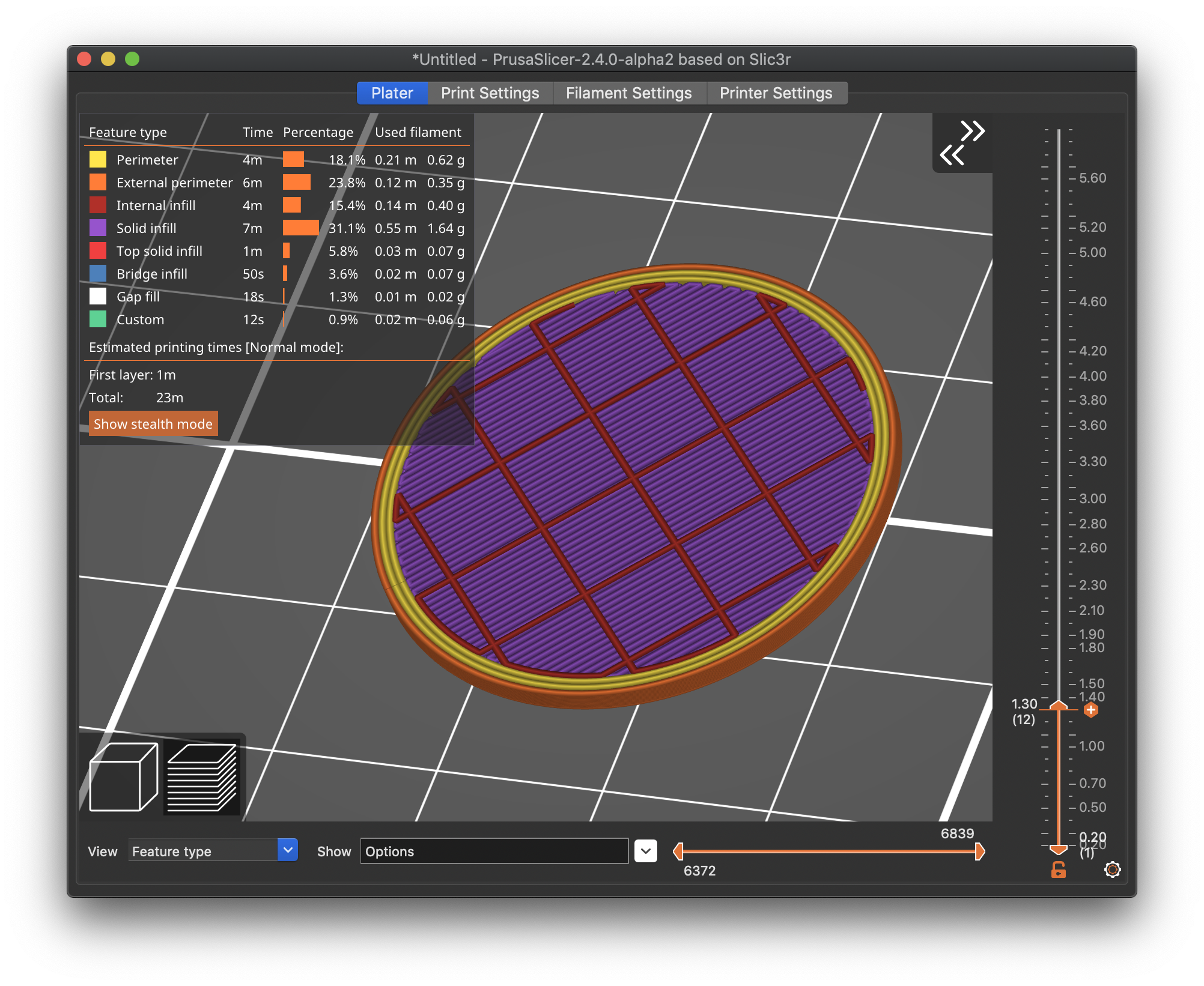
Most importantly, the top will print with enough layers to avoid the "pillowing" effect that results from printing atop bridges and infill with too few layers. The bridge layer printed atop the infill will be printed smoothly, and you can specify sufficient top layers to avoid the pillowing effect.

For this print with PrusaSlicer, I think this is your answer. If you don't like the way it works, stick with whatever slicer gives the best results.
So far as other issues: without knowing what settings you're using, we can only guess. It's always most helpful to see the full settings and part details to diagnose problems. If you'd save your current 3MF project file, zip it up, and attach it to a reply here, we can see your part & settings and give better recommendations, and you'll spend less time extracting, then cutting & pasting settings and renaming files.
Here's the zip you requested: W
The hollow space is for a magnet. Two bottom layers is plenty for a fridge magnet to be held in place and I did size the cylinder height to give the extra top layers to avoid the issue I'm asking about though I would rather not have to do that. It does seem to be the only solution though, which I think sucks because it's an ongoing problem I run into with various prints.
The issue at the bottom can be worked around by adding a secondary extruder and a range modifier (from 0 to 0.6 mm) where you select that second extruder (which of course doesn't exist physically) and turn off top layers. That will give you two solid bottom layers. At least I got that to work in the latest 2.4 alpha. Haven't tried in the release version.
Correction: You don't need to add a second extruder. A range modifier with top layers set to 0 seems to work:

Fixed. And Zipped
@r-2
See how easy that was.
Also notice the way I made the fixed file visible so you can notice it.
Regards
Swiss_Cheese
The Filament Whisperer
Your thicker top layer look promising
Here's the zip you requested: W
Thanks. That makes it a LOT easier to figure out what's going on.
The hollow space is for a magnet.
OK, that makes sense.
Two bottom layers is plenty for a fridge magnet to be held in place
Bottom layers can be thinner since they have something to squish against for good adhesion. I personally like them a bit thicker, but if you're inserting magnets, thinner makes sense.
and I did size the cylinder height to give the extra top layers to avoid the issue I'm asking about
I notice this version does have a thicker top layer below the lettering. It looks like you're printing the top at 3-4 layers thick now. Has that improved the top surface appearance?
though I would rather not have to do that. It does seem to be the only solution though, which I think sucks because it's an ongoing problem I run into with various prints.
Aren't we just talking about another 0.6mm of top thickness? Is that really a problem for the top surface quality improvement? IME, you want at least a few layers above any bridging above infill for best consistency across a variety of settings and filament types.
I notice at 4.6mm height (the 1st color change) you're still getting the split bridging, but it looks like it's sitting atop the inner walls well. Is that working well enough?
Different printer settings? Try printing PLA at lower temps perhaps?
[...] It does seem to be the only solution though, which I think sucks because it's an ongoing problem I run into with various prints.
Hey, I just realized you're not printing on a Prusa. Is that correct? Sometimes the 3MF import selects odd profiles. If so, your cooling setup might be very different. If you're having issues with top layer thickness, cooling is vitally important. I see that you've got your fan set to 100% for PLA, which is good, but you're printing PLA at 210C. That's a typical range, but you may be able to print PLA at cooler temperatures, which will help with cooling, which will help with top layer pillowing. Have you tried knocking 10-20C off that filament temp to see if you still get good results? This might also help with bridging results.
The upcoming PrusaSlicer 2.4 release (now in Alpha) has some bridging enhancement that might be useful.
@swiss_cheese : Now your layer 23 is even worse with 2 separations per bridge section instead of just 1. Nice try though.
@bobstro :
This is a fairly small example that is simple for showing the problem. In some of my other items that extra layer or two means time and filament. Not to mention the filaments that are semi transparent and that bridging can be visible. I don't really have a "pillowing" problem with the bridge itself so much as the solid layers above the infill won't always connect to the bridged section fully and the filament will curl down/up which causes the next layer to do various things. Then 2 more to smooth that out. If the pathing would combine the bridge with the solid infill it would have the same end result of a solid layer that bridged and look cleaner. The cooling and temps are for the modified printer I'm using and things turn out great on it, if I want lower temps I have to lower the speed, the flow/speed on the printer work out with this temp for a filament meant to print at 180-190.
2.4 alpha?
your going to have to change something in your specs if you need it any different, also are you doing this in 2.4 alpha?
I can make it go away but your magnet is showing 7.8 x4mm
Regards
Swiss_Cheese
The Filament Whisperer
Translucent layers atop bridging is tough
[...] In some of my other items that extra layer or two means time and filament. Not to mention the filaments that are semi transparent and that bridging can be visible. I don't really have a "pillowing" problem with the bridge itself so much as the solid layers above the infill won't always connect to the bridged section fully and the filament will curl down/up which causes the next layer to do various things. Then 2 more to smooth that out.
Ah, OK. Now I understand what you're trying to do. Sorry, I didn't have a clear picture before.
PrusaSlicer inherited some bridging behavior from Slic3r that produced notably ugly bridging results. This was done to get bridging to work at all way back when ABS was the primary filament, but things have changed. The thick bridging layer used up through PrusaSlicer 2.3.3 is going to look bad, particularly for translucent prints.
PrusaSlicer 2.4 (currently Alpha) has introduced new "thin" bridging behavior that shouldn't be as ugly, but -- after a quick test -- still doesn't do exactly what you're after in terms of pathing.
For transparency, there are some things you can do to improve transparency with thicker layers, but the bridge layer over the infill will still be a problem. There was a good thread here that might have some interesting tidbits, but you're bridging will still be an issue even with those techniques.
Is a 2 part print out of the question? If the top with letter could be printed flat on the bed, it sounds like it would fix a lot of problems. A snap fit design might not be much slower to produce, and you could swap on different letters without a full print if that's easier. Might also eliminate pauses for magnet insertion.
If the pathing would combine the bridge with the solid infill it would have the same end result of a solid layer that bridged and look cleaner.
Other slicers use different pathing. While I love PrusaSlicer, I still revert to ideaMaker or occasionally Cura for specific prints. That may unfortunately be your best bet if you want that degree of control. Definitely try out PrusaSlicer 2.4's options just to compare.
The cooling and temps are for the modified printer I'm using and things turn out great on it, if I want lower temps I have to lower the speed, the flow/speed on the printer work out with this temp for a filament meant to print at 180-190.
Makes sense. I just wasn't sure how it would compare to a Prusa. Unfortunatley, printing over thin air is a challenge with FFF printers.
Got to give to get
@r-2
As I mentioned before you will have to change your specs, to get this finish with no breaks in the top layers for bridging you are going to have to either give up some layer thickness, use a thinner magnet, or increase the height of the object, you can only ask so much of the space your providing, in my first attempt to fix the file I thought you were just looking to repair the very bottom second layer, because anything else with these constraints wasn't reasonable and the bridging doesn't represent an issue at 4 layers as small as this is.

I'm still trying to guess what it is your thinking you should be able to do here, but this is one smooth bridging layer and since I was working with your specs trying not to change the dimensions of any of the features I have adjust the layers in certain areas to get it.
Good Luck, that's all the time I have for this.
Swiss_Cheese
The Filament Whisperer
@r-2
Ok, I was wrong I found a couple more minutes for this after reading you were trying for transparent filament, I stand by what I said about not enough space, but this is one last option this space for "Transparency sake.
![]()
I removed the inner perimeters allowing me add back a bit of the top and bottom layer thickness and in my option providing a cleaner look for translucent filaments.
Regards
Swiss_Cheese
The Filament Whisperer