RE: Build my own MMU?
@nikolai:
Ok, good to know that the debries problem is actually not that bad.
@karl-herbert:
good to know! I will have a look into it. So far I only discovered mods on thingiverse and the prusa library. Danke!
RE: Build my own MMU?
I carefully looked at @karl-herbert's desgin. Really nice job!
There are a few things for which I don't get the purpose:
- Underneath the pulleys are holes. Similar to what I suggested in my recent post, but in karl-herbert's design they seem to have a different purpose as they are not located underneath the filament. Maybe to improve the stability of the part (because there are more perimeter walls)?
- The front PTFE adapter has a indent. Is it to give space for tolerances in the position of the z nut?
- Also there is more material in the region where the filament can be cut. I guess that holds the filament better in place when cutting. I did not get what the grid like structure in the gap is for. Looks a bit like support structure for printing, but why not use automatic generated supports?
- The blade cuts in both directions. In which cases is that helpful?
Here the full list of mods that I found, sorted by part:
pulley body:
- feed after pulleys: corner filleted
- almost everywhere: chamfer
- brass bar (Stützrolle): pulleys rest on it. This is to prevent the pulley shaft from bending.
- holes underneath Pulleys (purpose?)
- bottom slightly thicker
- iglidur at selector motor shaft end. Original: directly in printed plastic
mmu2 rear PTFE holder:
- filament input: Festo Adapter
front PTFE holder:
- concave indent towards selector. Maybe to allow tolerance on z nut position?
- wall before and behind location where the filament is cut, additional material as support structure for print (?)
idler body:
- ball bearing on opposite end of motor, original: just in plastic
- ball bearings on hinges, original: just shafts in plastic
- chamfers
- bottom slightly thicker
idler shaft:
- rings (Stellring) at end to screw idler shaft to motor shaft, original: two nuts in plastic
- chamfers
finda selector:
- finda mount more sturdy
- dual way blade (purpose?) additional screw
- above and below brass bushings: thicker plastic
- original: one brass bushings, modification: iglidur bushings
- additional magnet, to avoid false triggering of the sensor?
frame holder:
- chamfer
ELE assembly:
- reset pin: to push reset button
- second cover with mount for fan
- chamfer
Label MMU2S
- not at all on original
RE: Build my own MMU?
@christian-ho
Good overview. You have put a lot of effort into it.
To document every change in detail was too much work for me, because a lot is self-explanatory. The two-sided cutting function of the blade is only a safety option in the MMU2 misbehavior. Cut-outs are included so that the cut-off filament tip does not get stuck in the MMU2 and accumulate over time. Ideally, a catch basket could be designed for this purpose.
So that everyone, which intends to revise the MMU2 also, STEP files of the entire unit uploaded (MMU2_Unit_Assembly.stp).
I look forward to new ideas, suggestions for improvement and feedback on this.
Statt zu klagen, dass wir nicht alles haben, was wir wollen, sollten wir lieber dankbar sein, dass wir nicht alles bekommen, was wir verdienen.
RE: Build my own MMU?
I want to make a change to the filament input /PTFE connectors:
While I do like the option to have all tubes easily removable, I would prefer such ones with a bigger diameter.
Currently I have my filament in a box that protects it from humidity and dust. When I print something, a PTFE tube guides the filament to the printer. I observed that in 4mm OD, 2mm ID tube can cause quite some friction, so I switched to 5mm OD, 3mm ID tube which is much better. (At that time, I was not aware of 4mm OD, 2.5mm ID tube.)
My modification to the input allows to use tubes with an outer diameter of 6mm. (Modifying for 5mm is simple)
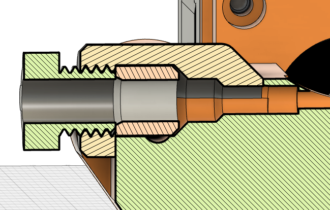
The ring fits tightly around the tube. The screw holds it in place. A short 4x2mm tube towards the pulleys guides the filament the remaining way.
I will certainly have to chamfer that tube input, to get the filament loaded from the bigger tube. Maybe the transition fom 6x4 to 4x2 is too much, so maybe I will have to add another piece in between, or work with 5x3mm tube from the beginning.
Tested so far:
- The ring really holds the tube well.
- Screw and nut are printable in this dimension and are certainly stable enough (although hollow).
RE: Build my own MMU?
@karl-herbert:
forgot to mention: I used your STEP file to find the differences. I loaded both versions (yours, prusa) into fusion and was easily able to compare them. That is a lot easier than just with stl files. So thanks very much for sharing the STEP!
Short update:
I almost entirely used all the changes you made to the part PTFE front holder. I also used your way to generate support material. I was not able to get slicer to do it in a way that seems convenient.
One change I made:
The end of the hole is now chamfered. I would expect problems during the print if the change was just horizontal.
One question: Did you enable supports when printing the pulley body? Or how can this part of the print succeed?
I implemented the support of the pulley rod differently. I copied many features of this mod:
https://www.thingiverse.com/thing:4441611
The filament is guided closer to the pulleys, also plastic supports the pulleys. Although there is only contact between plastic and pulley in regions where the pulley is smooth, I don't really feel comfortable with the pulley permanently moving over the plastic. I'm wonderung: Isn't that a problem for the brass rod, too?
RE: Build my own MMU?
@christian-ho
I almost entirely used all the changes you made to the part PTFE front holder. I also used your way to generate support material. I was not able to get slicer to do it in a way that seems convenient.
For this reason I have constructed the support for it.
One question: Did you enable supports when printing the pulley body? Or how can this part of the print succeed?
No, I have not. I have mostly designed the holes this way for this reason:
The filament is guided closer to the pulleys, also plastic supports the pulleys. Although there is only contact between plastic and pulley in regions where the pulley is smooth, I don't really feel comfortable with the pulley permanently moving over the plastic. I'm wonderung: Isn't that a problem for the brass rod, too?
The linked change is certainly a good idea, which could be included. The brass rod I regularly give a few drops of oil.
Statt zu klagen, dass wir nicht alles haben, was wir wollen, sollten wir lieber dankbar sein, dass wir nicht alles bekommen, was wir verdienen.
RE: Build my own MMU?
TL;DR: I have a question: Can someone tell me how far the filament is pulled back during a normal unload? I mean: at which exact spot will it stop?
I started to plan how to make the filament sensor on the MMU reliable.
My favourite is currently 2 ball bearrings enclosing the filament. Similar to the filament diameter sensor presented by Thomas Sanladerer. ( at 9:18, you can see a cross section of the sensor)
It would be a LOT easier to design it, if I could move the sensor a bit further out. But there I see a problem: When unloading filament, the MMU will have to pull it a bit more from the point, when the sensor does not detect filament anymore. As far as I can see, that would mean a change in the MMU firmware. I would really prefer not to do that.
Anyway, I looked into the source code and tried to locate where the filament is unloaded, and where the extra movement beyond finda happens.
I found several places:
(1)
https://github.com/prusa3d/MM-control-01/blob/master/MM-control-01/motion.cpp
line 127.
Once the sensor does not see the filament anymore, the firmare will do 99 steps (line 129, 141).
However, if the predefined number of unload steps were executed, the loop also stops. So the FINDA seems more to be a fix in case of some failure?
(2) After that, it does 100 more steps without condition.
See line 529 of:
https://github.com/prusa3d/MM-control-01/blob/master/MM-control-01/mmctl.cpp
At this point the filament should have passed the sensor. Otherwise the mmu will try to unload again.
(3) Now finally another 450 steps (same file, line 641) are moved.
The pully diameter is: 6.3mm
450 Steps is ~45mm.
This means the filament is at least ~2mm before the end of the PTFE tube between pulley and selector (still inside the tube, 2mm from the end that is towards the pulley)
So the 450 seems to be the magic number that I have to change. (BTW: Code with lots of magic numbers everywhere is really annoying!)
What puzzles me: If the loop (see (1)) gets aborted by FINDA, the filament will move 650 steps. This is ~65mm and will bring the filament behind the pulleys (= unloading even from the MMU / ejecting).
So this will definetively require the user's attention, but at this point no error is generated. Is this a bug or a feature...?
Anyway, at this point I am really not sure if I did a mistake when analyzing the code. Therefore: my question from the beginning of this post.
RE: Build my own MMU?
Hi,
Can someone please tell me: how does the mmu2s find the end position of the selector? Does it move towards the motor until it registeres the stall? Or towards the other direction?
Update on my development:
This is my current idea how my filament sensor on the selector will look like:
there are two ball bearings. the lower is fixed in place, the upper is on a leaver. the filament comes in from the left side and pushes the upper ball bearing upwards, thus also the leaver.
The leaver extends a bit further out, so it moves a longer distance. the 1.75mm of filament moves the end of the leaver by ~4mm. I hope this will allow a very reliable operation. Still, I will have the position of the light barrier adjustable, so I can do fine tuning.
I will use the EE-SX1025. It has a narrow transition (0.5mm from light path is fully open to fully blocked). Also it was available on ebay...
Comments are welcome!
RE: Build my own MMU?
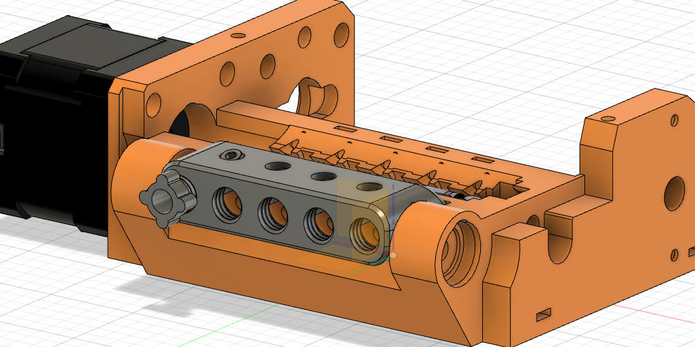
Short update from me: I started printing the parts. Although I am not 100% done designing...
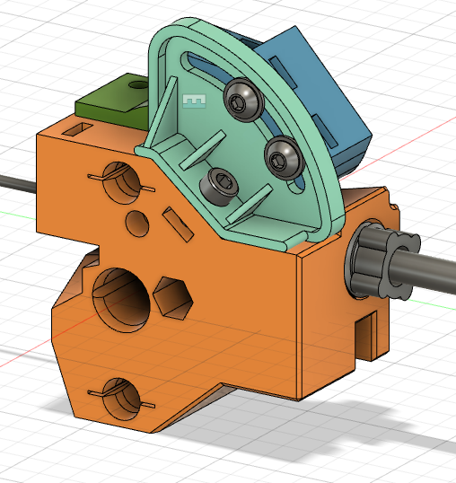
Here an overview of the MMU unit.
The filament selector, sensor adjustment parts, printed ptfe tube holder.
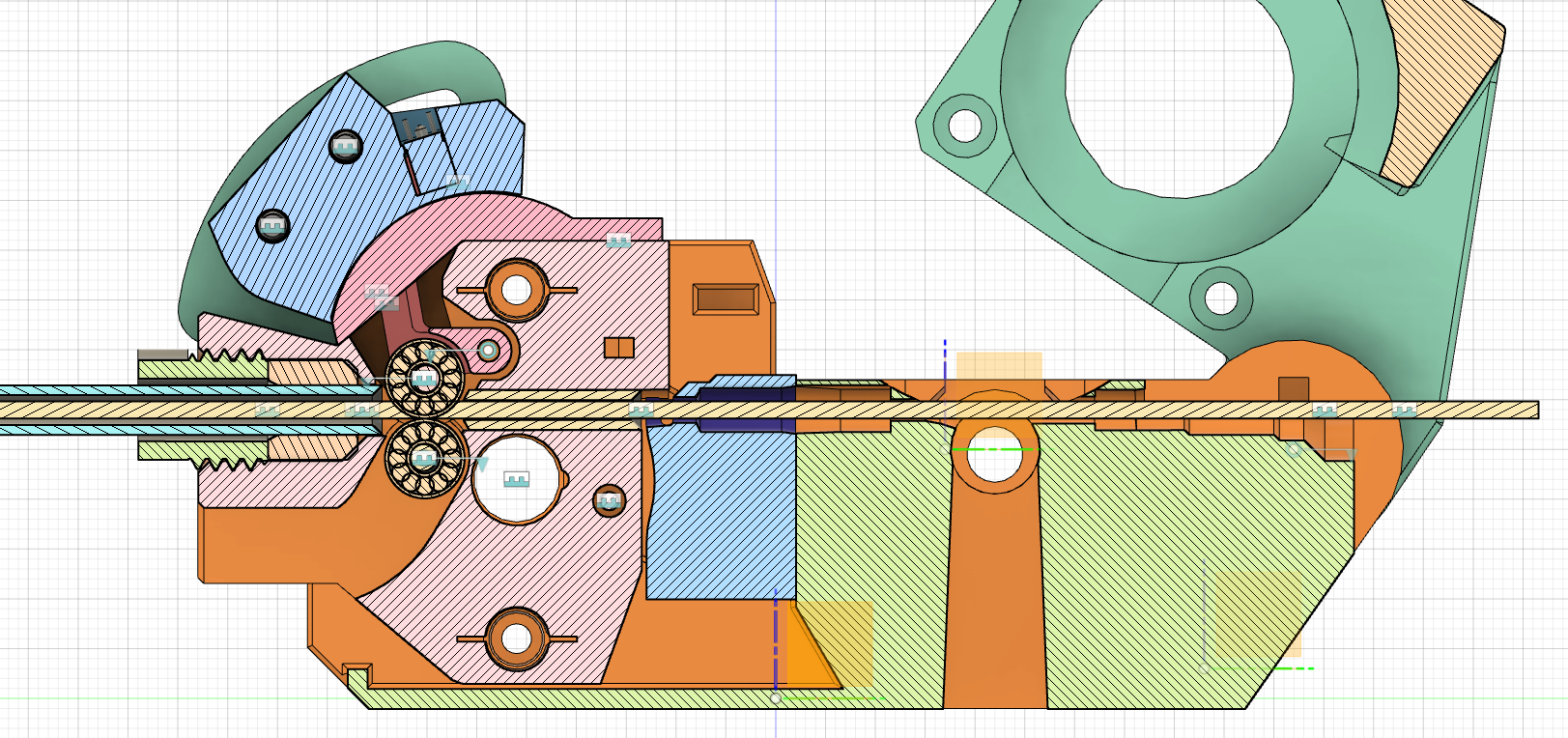
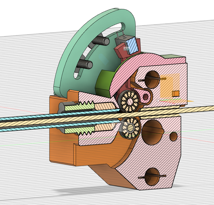
cross section through the selector.
the lower ball bearring is fixed in place, the upper will be pushed up by the filament and move the red leaver, which blocks the light path of the photo interrupter.
More updates will come.
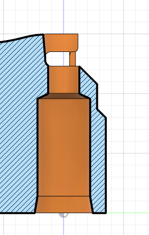
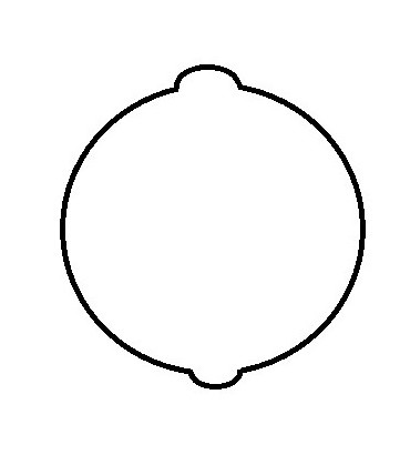
P.S. one question: does anybody know the purpose of these hexagonal pockets:
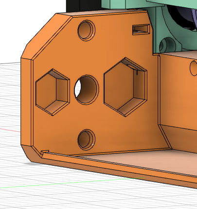
There does not seem to be a part of the selector that moves into those. Stability maybe?
RE: Build my own MMU?
@christian-ho
Interesting design! I am curious how this will prove itself in practice!
The hexagonal slots are most likely material savings.
I would support the sensor lever possibly with two neodymium magnets, so that the gravitational forces are strengthened and it reacts reliably and quickly.
Statt zu klagen, dass wir nicht alles haben, was wir wollen, sollten wir lieber dankbar sein, dass wir nicht alles bekommen, was wir verdienen.
RE: Build my own MMU?
I'm really curious, too. 🙂
Thanks for pointing out the idea with the magnets! In the beginning I planned to have an option to add a spring, but aparently forgot it at some point. Fortunately I did not print these parts yet. Adding the magnets is probably simpler than adding an option for a spring....
RE: Build my own MMU?
I'm trying to figure out how to add the magnets or the spring.
But first of all, how large should the force be?
My considerations: The leaver with screws weighs about 3 grams, which means the leaver is pushed downwards due to gravity with a force of roughly 0.03N. (I'm neglecting here that some weight is also supported by the hinge. As I only need the right order of magnitude, this approximation is fine I think).
Applying a force of just 0.3N should immensely speed up the reaction of the leaver (If applied by a magnet or spring, not additional weight. -> inertial mass vs gravitational mass)
Of course the force needed also depends on the position where I apply it. I should rather calculate with torques instead of forces.
I also don't want to go too high with the force as I want to be able to use very soft filament. So it needs to be able to move the leaver while not leaving the path.
However, this is based on the assumption that the purpose of this pretension is only to speed up the reaction of the leaver. If it is important for other purposes (maybe squeezing a bad filament tip just enough that the sensor does not detect it anymore) then my result is not relevant.
I had the impression, that getting good tips when unloading is well under control, at least with modified ramming settings.
But maybe I am missing something?
RE: Build my own MMU?
very short update:
I changed the filament sensor, printed, assembled, tested...
The current design uses a spring to push the leaver back. I like springs better because their force changes slower with the displacement that for a magnet / metal combination.
I built a torstion spring myself with 0.4mm spring wire (not really difficult, tutorials and formulas for dimensioning the spring are all over the web)
Here is a rendering of the sensors insides:
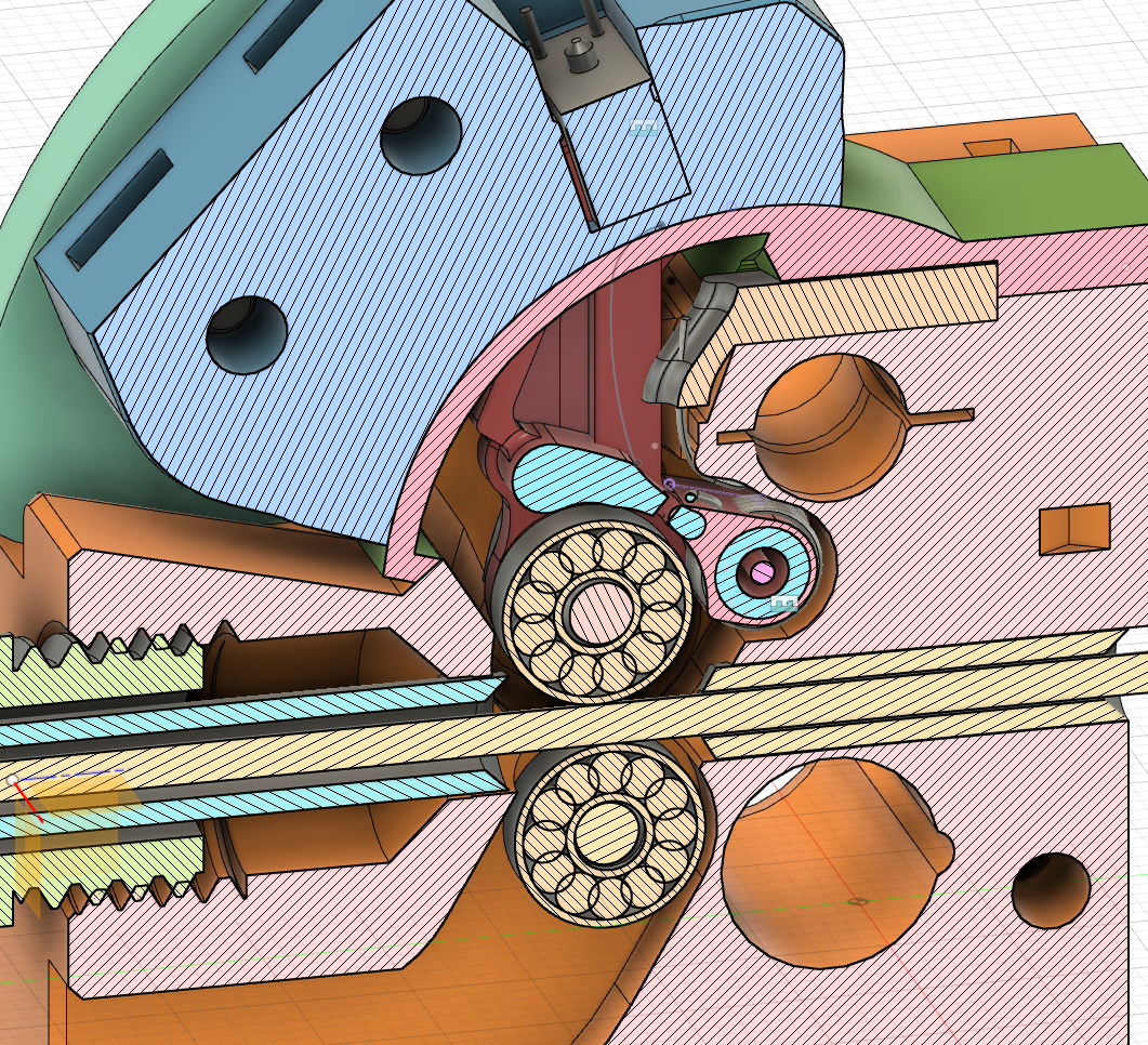
the spring is wound around the hinge of the leaver. its shaft is 2mm, in the picture is 1mm i think...
above is a small leaver to set the spring tension, which I most likely will never have to use.
everything is printed and assembled already. So far it works quite well I think. Filament goes through it really easily. I pushed the filament through the sensor with a kitchen scale. The maximum reading was ~30g (50g before I modified the spring).
For comparison: the softest filament that i have is flexfill TPE 90A. When holding it ~ 5..10 mm before the end and pressing it against the scale, it folded itself at ~300g.
what i would do different next time:
- print the leaver as one piece with support material (I printed it as two pieces and they dont match perfectly)
- make the hole for the shaft bigger! I used 2.2mm for the 2mm shaft but it turned out smaller (which puzzled me a bit me as other holes turned out spot on, probably it depends a lot on wall thickness, stuff behind the wall of the hole,...)
- make the leaver a bit thinner. on the tip it is 2.4mm while the gap of the photinterrupter is 2.8mm. the leaver got stuck in the beginning, but now moves smoothly after i smoothed the surface. Still this might turn out as a source of problems...
- add a guide to the holder of the photo interrupter adjustement thing (turqoise part)!! When screwing it tight, it can turn a little, which misalignes the gap in the part with the photo interrupter (bright blue part). then the leaver really gets stuck..
- one small mistake: I tried to get it rater light tight. Turns out, the photointerrupter is open on the bottom which is entirely uncovered so far, so currently it is not light tight at all. But that seems fixable...
Anyway, I am happy with the progress so far...
RE: Build my own MMU?
So... I still have to build the extruder upgrade.
The original MMU2S uses the displacement of the idler caused by the filament as "mechanical input" for the sensor. I think this is a very good idea. However, I think the magnitude of the leaver movement is too little. The leaver on my MMU selector moves ~4mm, which allows quite some tolarance while still having certainly the light blocked or certainly open. Even if the exact detection threshold changes a little (which is unfortunately a thing light barriers do), I am convinced that the large amplitude of the movement will still ensure reliable operation.
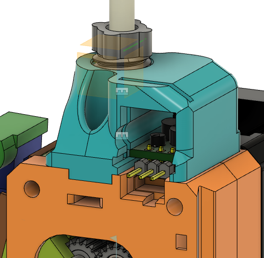
Here my current idea for a concept to increase the leaver amplitude for the filament sensor on the extruder:
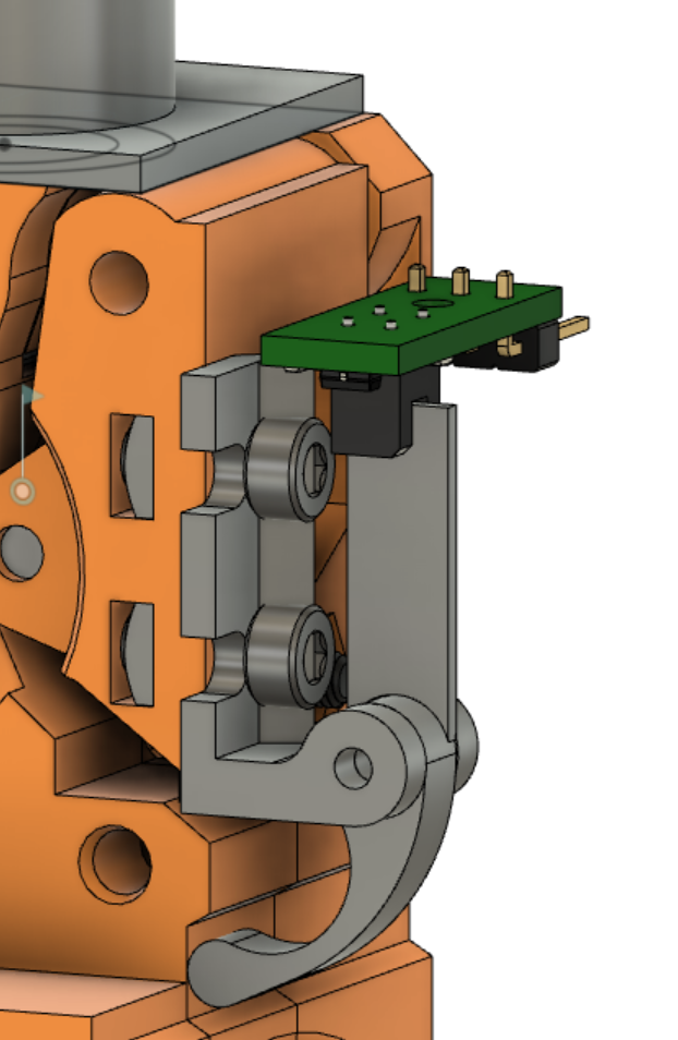
certainly there is a lot of detail work that I still have to do:
- make sure it fits and does not bump into the z axis when moved to the end of the x axis, maybe modify.
- add a spring so the leaver gets pushed towards the extruder assembly
- make it somehow adjustable
- close it, add something to mount the light barrier.
- change the screws that connect the leaver holder to the idler door. might not be stable enough like this.
- maybe i can modify it even, that I can print the idler door and the part attached to it as one piece? So those 2 screws are not necessary...
What I like about this idea: The idler door can still open all the way. That is not possible with the tower of the MMU2S if I see it correctly.
RE: Build my own MMU?
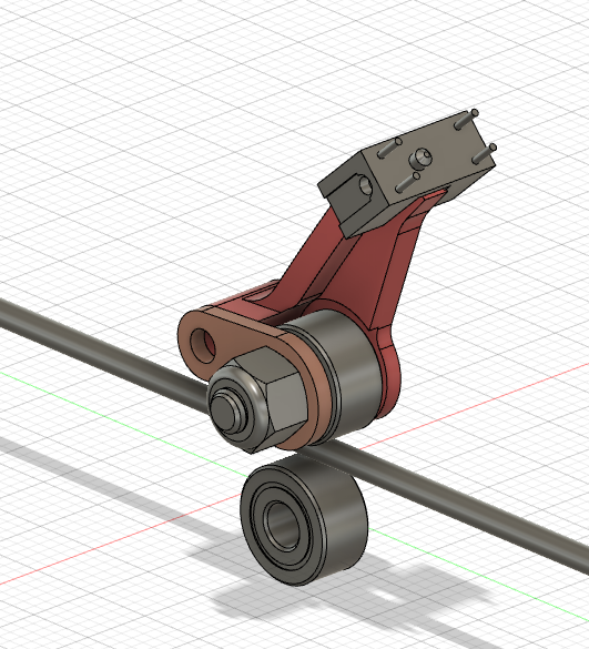
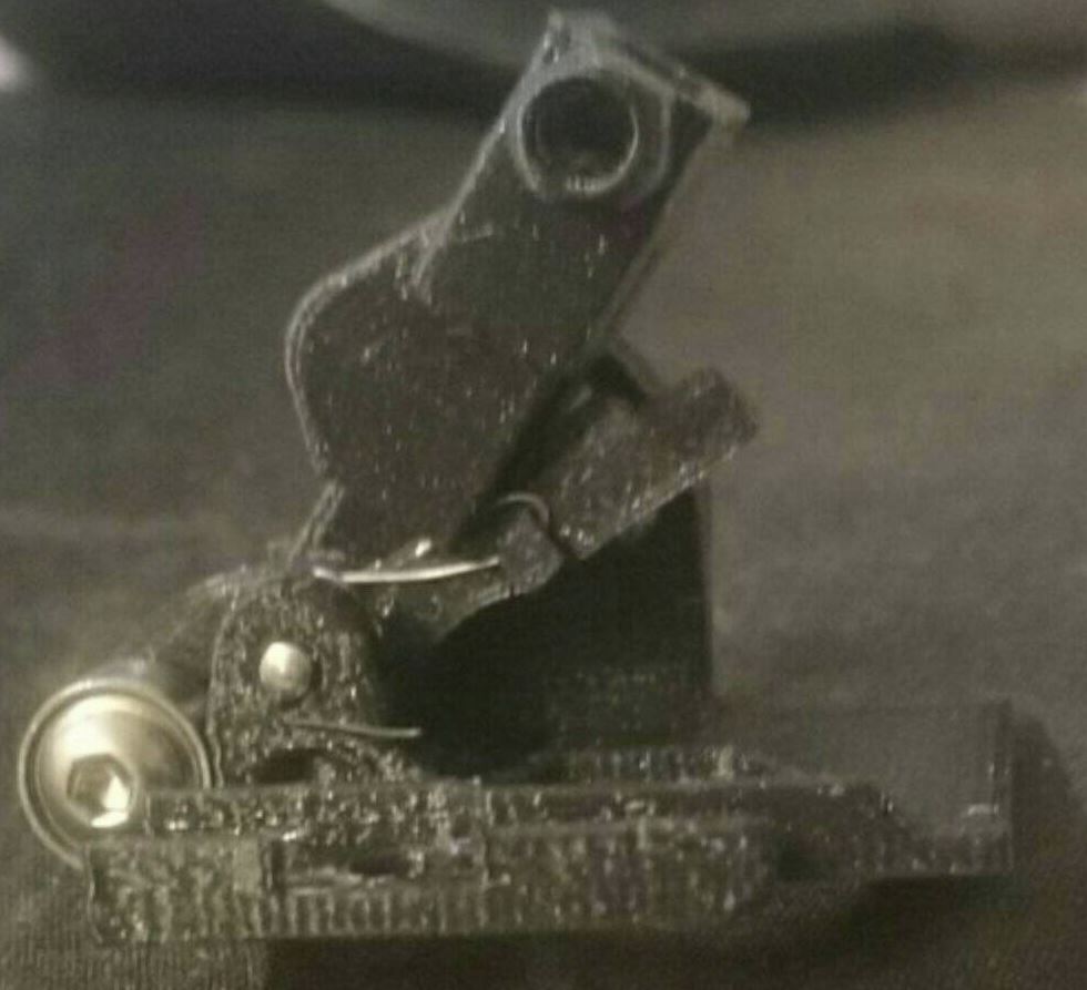
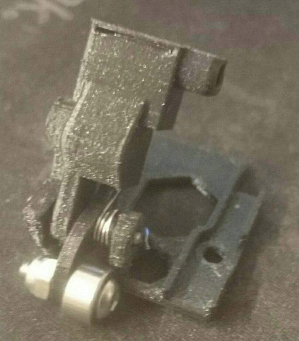
Short update: Making progress on the extruder.

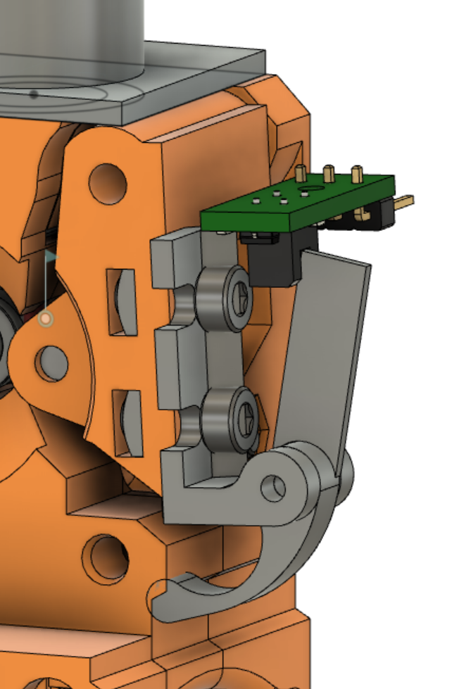
a part is attached on top of the normal idler.
an ir sensor is inside the blue-purple part. its position can easily be adjusted.
a leaver (red) senses the position of the idler door.
compared to the sensor in the selector, I changed somehting: the leaver is only on one side of the ball bearring. the force is low enough that the leaver gets not bent. much easier to print and also more stable as i can make the leaver thicker.
the cylindrical part on the leaver (around the axis) is necessary (and sufficient) to avoid the leaver from tilting / moving in any direction it is not supposed to.
a spring presses the ball bearring against the extruder body.
when the filament is removed, the door mooves a bit inwards. so, from the idler door's perspective the extruder moves outwards and pushes the ball bearing away, therefore moving the leaver.
again, the sping is custom made (which is really not that difficult) and the mechanism seems to work fine. at least outside the printer.
(sorry for bad picture quality)
still todo: finish the tube connector on the extruder, assemble, test! 😀
RE: Build my own MMU?
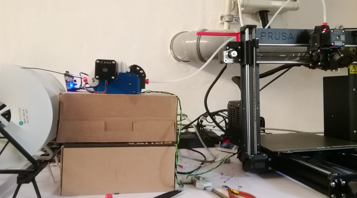
A few assembled parts.
MMU unit:
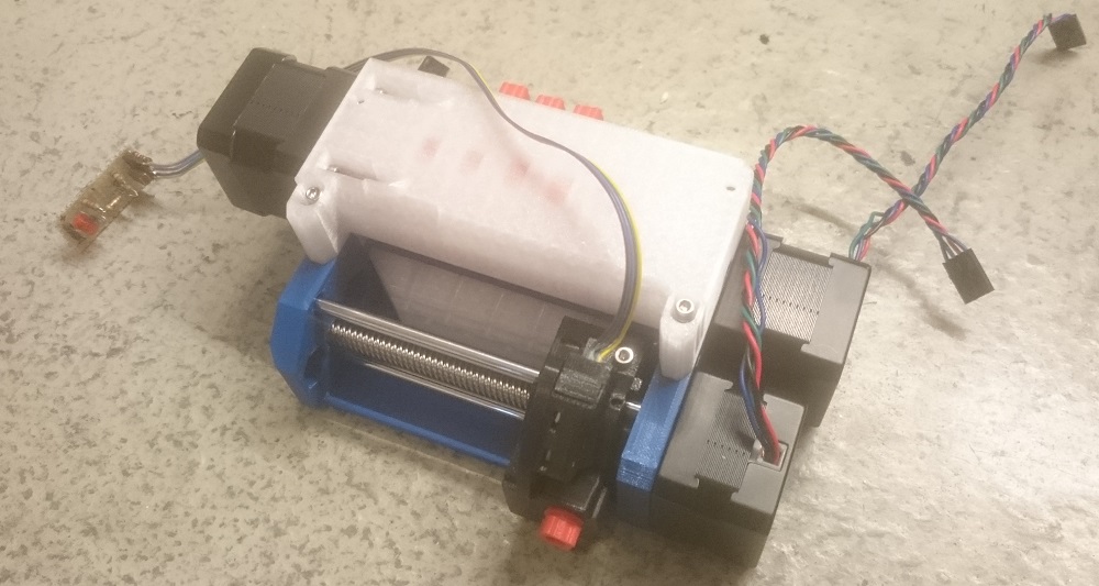
Upgraded extruder:
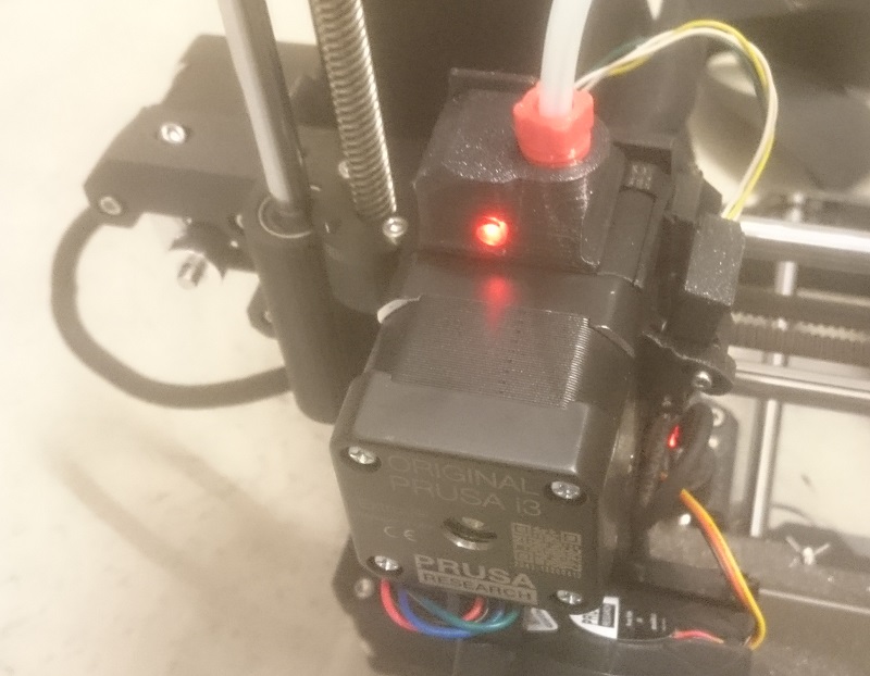
LED on = no filament present.
Currently I am operating the printer only with the new extruder as a normal i3.
I still have to make the cables that connect the MMU controller board to the Rambo board and unfortunately can't do that right now.
The sensor on the extruder works ok so far. At first, I had problems getting the filament inside at all or out after the filament was loaded into the extruder. So in increased the size of the hole in the part "adapter printer". Now it is 3mm. Maybe I will have to do another revision on these parts.
As I am operating the printer as an i3, there is no special procedure when unloading the filament and the tip looks pretty messed up. However, loading and unlading worked good after the last changes (4 times so far). Sometimes I need a little force to pull it out, but I guess that will be better when the filament is unladed in MMU mode.
Also, the leaver on the side (the one blocking the light path of the IR sensor) was stuck in the beginning sometimes. I incresed the tension of the spring a little and also no further problems.
The circuit of the IR sensor is roughly at the same spot at the original printer. (However, my IR sensor is in the leaver on the left with the green lid)
P.S.
I inserted a wrong picture on the last post. here the right one:
RE: Build my own MMU?
I assembled more and was able to load the filament to the extruder (via MMU) all the way to the extruder for the first time today! It worked!
A thing I had to fix before was my extruder filament sensor. I mixed up the polarity of the signal. On the selector, '1' means filament present on the extruder sensor, it is the other way round...
Maybe homing did fail sometimes on the MMU part in my first attempts, but maybe that was only an user-to-stupid error. Currently it seems to work flawlessly.
Here are some pictures:
I already "calibrated" the bowden tube length to feed the filament faster. Btw: I have reached the maximum setting. When the end of the filament is a few cm above the extruder, the MMU won't change the position anymore. I could change the firmware for that, but it is anyway so little that I don't really see the need.
As you can see, there are still some things to do:
- Print the enclosure for the PCB
- Print / design a mount for the MMU (I want it to be outside the printer enclosure)
- Decide / implement auto rewind spool holders or a proper filament buffer.
- Start proper testing which includes printing.
- Maybe add a purge bucket?
A problem that I saw already: My filament is extremely stringy! After unloading there are like 4 cm of stringy debries on the tip. That is such a mess that even the cutter does not really solve it.
I know there are better unload settings, but do those only affect the unloding during a print? Or is there a way to use those also during manual load / unload?
Anyway, so far I am happy with the overall progress and the current status.
RE: Build my own MMU?
First print, first problems...
Here is a picture of the first thing that I printed - the frame of the controller pcb:
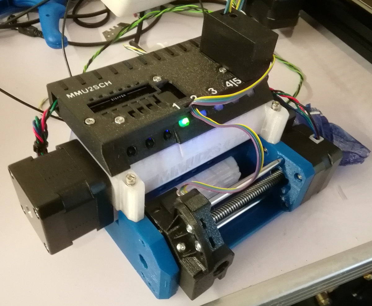
Multi material about it is the transparent windows in front of the LEDs (to scatter the light) and the labels on top.
I guess it is not a surprise that everything did not work flawlessly on the first attempt.
Here a list of problems that I still have to solve:
1) The pulley did not grab the filament properly. I encountered that it didn't grab the filament at all, but also that it carved a notch into the filament.
I wonder:
- Do I just have to find the proper strength for the idler being pressed on the pulley?
- Maybe one modification that I implemented makes things acually worse. I mean the one that I found on thingiverse: the filament is guided much closer to and from the pulley. The filament still needs to be able to move a little when the ball bearing on the barrel presses it into the pulley. Maybe The additional guide is in fact an obstacle?
2) During one unload, the filament was stuck in the extruder. Even though the filament sensor on the extruder still detected filament, the MMU tried to pull it out. Maybe that was when the notch was carved into the filament?
I have no idea what I can do about that issue. I should have taken notes on what I found when I opened the extruder to release the blockage....
3) At some point, the idler lost its home position. The ball bearings were not pressing against the pulley anymore. From then on, I had basically to do all the load / unload manually.
Is there a way to re-home during a print?
4) The tips are still quite stringy. This eventhough I already use the settings recommended by @Thejiral. Hopefully switching to a different filament will solve this. I also observed in normal prints that this filement is quite stringy. Maybe I should also turn down the temperature or print a temperature test tower.
5) When I turn it on, the MMU makes scary noises, like somerhing is cracking. Maybe this is the homing of the barrel? Is it supposed to be so loud? I thought about trying an alternative firmware:
https://github.com/TheZeroBeast/TZB-MMU2S-Firmware
Anyone has experience with it?
RE: Build my own MMU?
TL;DR: working fine now!
Detailed update:
One big problem was that the shafts that connect the idler body, with the lid, came loose. The shaft went out, so not a big surprise that the pulleys were not grabbing the filament anymore properly.
I fixed that by adding a washer to the screw that secures the shaft. Also I heated and squeezed the plastic a little so the shaft is sitting more solid in palce.
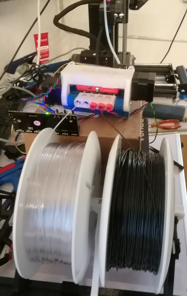
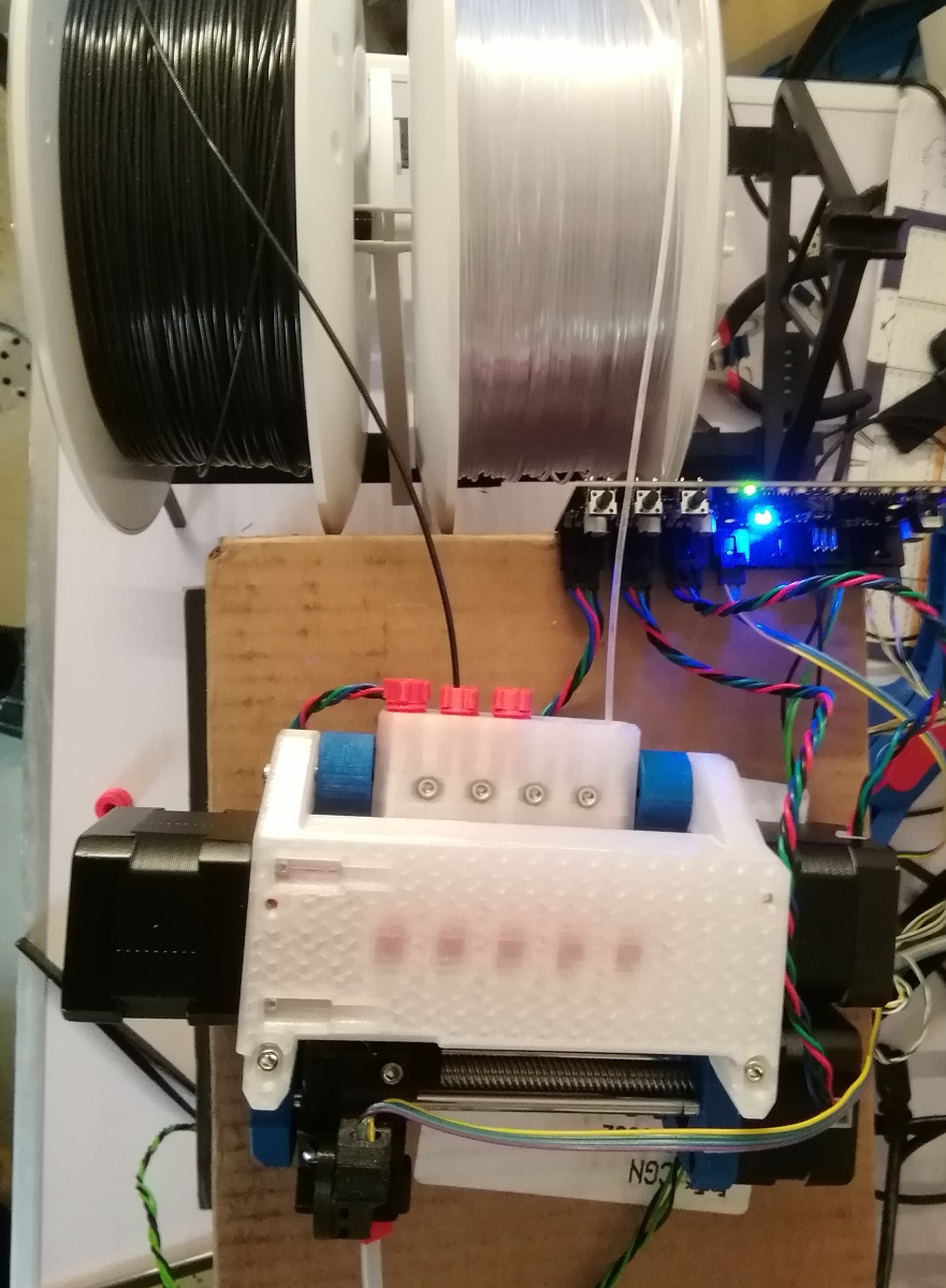
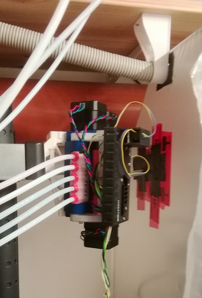
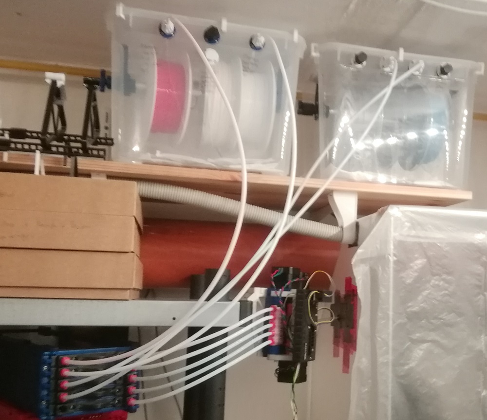
I decided for a filament buffer and not rewind spools. I decided that way as I can have now much more than 5 spools in my dry boxes but still only have 5 "channels" of filament backfeed handling.
I modified this one: https://www.thingiverse.com/thing:4154364
My mod is longer (I need to store more filament as the mmu is outside the enclosure), has all inputs on one side, uses my printed tube lock screw and 6mm ptfe tube.
The firmware by the zero beast is amazing btw. Also it seems to be up to date to the original prusa firmware quickly after a new one is released (you need to use custom firmware for printer AND mmu).
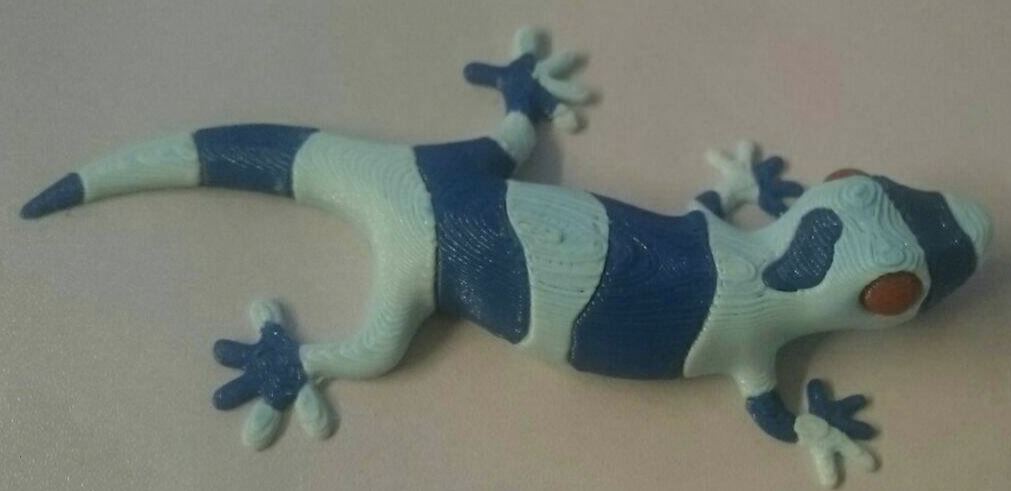
I printed the lizzard as my first "true" multiclolor print, that does not only have a hand full of tool changes.
My first attempt failed. I forgot to use the right unloading settings.
Why is that a property of the filament?! I think that is really stupid. It is certainly usefull to be able to override settings for specific filaments. However, I would like to have the basic settings in the printer properties. Like this I have to modify every single filament. I see it comming that I will forget to select the right settings there again and ruin another print...
What I also realized: The interface beween different material sections is very brittle.
I think the reason is, that it is infact printed as separate objects, having perimeters to each other:
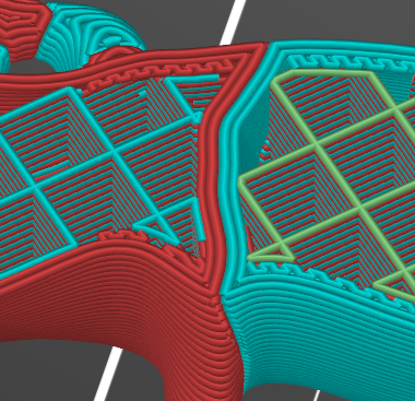
So internal borders between regions are treated as external perimeters.
Is there a simple way to improve this?
Ideas:
- not print a perimeter there, instead continuos infil (which will have a random color)
- print that part with much higher temperature, to the layers fuse better to each other
- have not a straight vertical interface but a zig zag shape / interwoven
options 1+2 probably have to be done by the slicer. Maybe there are somewhere already features that do that? Does anybody know?
option 3 I can do myself when designing a part.
con:
- I need to decide already at design level what layer height I want to use. This will be probably tedious work to do.
pro:
- I bet that will be a super solid connection, outperforming options 1+2
- I can do that myself, no need to modify the code of slicer.
Finally some pictures:
As the movable part of the filament sensor in the MMU is spring loaded, I can use it in any orientation 🙂
Finally: a big thanks to everyone who gave support here, by commenting! Thanks to @karl-herbert for mentioning his mmu modification (of which I used many aspects) to @thejiral for sharing his unload settings with the default unload settings, the MMU would just be unusable, which i realized in my first attemt to print the lizzard), and to @nikolai for convincing me to modify the prusa version instead of building one from scratch (If I would have done that, I guess I would not be even close to have a working system right now)
RE: Build my own MMU?
@christian-ho
That rig to measure filament diameters is a great find. I am very impressed with the findings for Prusament and it stands with my experiences.
I have been following your design and hope you continue to find success. You should share with the DEVs for Prusa.
--------------------
Chuck H
3D Printer Review Blog