some corrections
One correction regarding the motor connector if trying to match that on the Moons motors.. It is a 0.2 mm pitch, six position, JST-PH.
Also, did further revisions on the extruder and now I don't even need to remove the back bearing cover to change motor.
Re: Stepper Motor Upgrades to Eliminate VFA's (Vertical Fine Artifacts)
I printed a test file that was sent to me by guy.k2 and took some pictures after I printed it with the bondtech extruder.
Printer: Original Prusa I3 MK3 with sensor upgrade from MK3S
Extruder: Bondtech BMG geared 3:1 with 0.9 ° LDO stepper
Filament: Silver PLA from Filament PM (same that shipped with the printer)
Firmware: https://github.com/bgiot/Prusa-Firmware-BMG using 16 microsteps instead of 32
Camera: Sony Alpha A7R III with 42 mpix
Lighting: flash with and without softbox
To turn this into a somewhat scientific test, I used my photostudio and photographed the front and the side piece of the tower from 3 slightly different angles each, using both a diffuse light from a softbox and a direct light from a bare bulb (both from the front and from the side). The files are named accordingly and there are two overview pictures to show you the setup of the light. The flashlight was used as a focus aid for the camera.
I also took pictures of an old ECOR tower I printed with the MK3 stock extruder as reference. It clearly shows VFA. I never adjusted the ECOR settings after the print, as I didn't see any significant difference between the stages.
I noticed that increasing the clarity in lightroom (micro contrast) makes the VFAs become much more visible. I therefore exported a second version of the old ECOR tower pictures and some of the new test prints again with increased clarity. (files named accordingly)
All files can be downloaded in native 42 Mpix resolution from here:
https://drive.google.com/drive/folders/1mCHXkwJyBG-Jr8sEJzB1c9geEyUzjdTm?usp=sharing
SUMMARY:
-My old ECOR-Tower shows significant VFAs when printed with stock MK3 extruder.
-Prints with the Bondtech extruder show no VFAs
-The visibility of the VFAs does not stronngly depend on lighting, quick mobile phone pictures can be as good as studio pictures taken with professional equipment.
-increasing micro contrast (called clarity in lightroom) increases the visibility of the VFAs
Please let me know if you need any other test prints and/or pictures.
Re: Stepper Motor Upgrades to Eliminate VFA's (Vertical Fine Artifacts)
Thank you! Thank you! You've provide a huge cache of info we have never had about the Bontech. Will be looking through your picts with keen interest.
Re: Stepper Motor Upgrades to Eliminate VFA's (Vertical Fine Artifacts)
Did you have any issues with vibrations or loud noise?
I bought a higher torque version with higher inductance, I wonder if the high inductance might be limiting the speed somehow. It's so noisy though, any ideas/thoughts?
I'm still playing with the current a bit, but still not sure what. Maybe poor motor choice, hmm...
Re: Stepper Motor Upgrades to Eliminate VFA's (Vertical Fine Artifacts)
Still need to download the Bondtech tower images to look at them with full resolution. Really love that you used a good camera. Am I correct in saying all the new ecore towers were done on the Bondtech extruder? The old style tower was on the stock extruder, but never on the Bontech.
=====
Got busy tonight retuning Stallguard Homing reliability with 0.9 degree motors. My firmware should now be more tolerant during homing with varying belt tension and z-height. Counterintuitive, but Stallguard homing works better with a slower velocity hit against end stops. Anyone using my firmware for 0.9 degree motors should grab tonight's update.
Re: Stepper Motor Upgrades to Eliminate VFA's (Vertical Fine Artifacts)
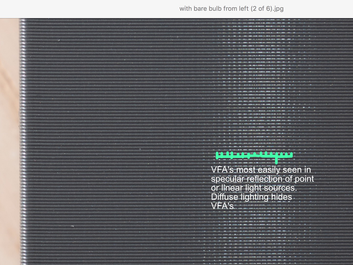
Spacemarine, thanks for all those high resolution images. Unfortunately, you took a lot with lighting that tends to hide surface artifacts rather than enhance their visibility. The more specular reflection we get, the easier it is to see what is of interest. Bare bulb or flashlight is most revealing. Also, can you print in PETG? The glossy finish helps make things more visible.
For instance, in the one image that shows specular reflection, you CAN see the VFAs. I didn't expect the Bondtech to make VFAs disappear. Those are x and y motor effects that are not changed by the extruder. They are present. It takes the right lighting to make VFA's visible. Soft box hides it well.
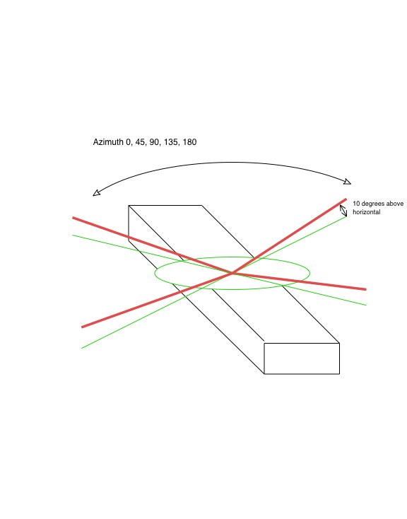
Lighting angle makes a huge difference for capturing surface artifacts. For getting surface diagonal wave, I recommend using a flashlight at 10 degrees elevation with various azimuths every 20 degrees from -90 to +90. Ignore labeling in pict showing different azimuth range. Idea is to get enough azimuth angles that we have lighting at right angle to possible wavefronts.
Re: Stepper Motor Upgrades to Eliminate VFA's (Vertical Fine Artifacts)
Did you have any issues with vibrations or loud noise?
No. Both stock and bondtech were extremely quiet, but I probably also have the best mechanical decoupling possible (that is affordable). Just in case it matters, here is a small clip of the setup. The printer is placed on a heavy stone that is placed on a air-filled bycicle tire. Very safe and stable. This results in the lowest resonance frequency of the printer I have seen so far. It is the same principle (just without the active dampening) as is used in optical tables to isolate them from building vibrations.
https://drive.google.com/file/d/1zhu3SNvSHt9vt7pBVI4hePF7Av0f3wth/view?usp=sharing
Re: Stepper Motor Upgrades to Eliminate VFA's (Vertical Fine Artifacts)
Am I correct in saying all the new ecore towers were done on the Bondtech extruder? The old style tower was on the stock extruder, but never on the Bontech.
Exactly right. I have rearranged the pictures into subfolders to make this more clear.
Will print PETG tonight and take pictures tomorrow as instructed. The camera should be placed perpendicularly to the layers and just the light will be rotated?
Re: Stepper Motor Upgrades to Eliminate VFA's (Vertical Fine Artifacts)
The camera should be placed perpendicularly to the layers and just the light will be rotated?
Yes, perpendicular to plane for capturing the diagonal extruder wave.. Only one of the large planes needs to be photographed, but get multiple azimuth angles.
For VFA's, the camera has to be positioned to catch the reflected gloss, but we already know about the VFA's being present from one of your original picts.
Big thanks again for gathering this data for us.
Re: Stepper Motor Upgrades to Eliminate VFA's (Vertical Fine Artifacts)
Big thanks again for gathering this data for us.
I'm happy to contribute to this. I've followed this thread from the beginning as it is a perfect example of the benefits of an open-source community.
Re: Stepper Motor Upgrades to Eliminate VFA's (Vertical Fine Artifacts)
BTW, don't forget to add heatsinks to the TMC2130's if using 0.9 motors.
Do the heatsinks fit ok inside of the electronics case?
Would these work:
https://www.watterott.com/de/Stiftkuehlkoerper-quadratisch-ICK-S-10-x-10-x-125
Motor Inductance
I bought a higher torque version with higher inductance, I wonder if the high inductance might be limiting the speed somehow. It's so noisy though, any ideas/thoughts?
It is a mixed bag on the Prusa Mk3. Higher inductance means more back EMF and yes, limits absolute max speed. On the other hand, the Mk3 is not a delta printer and doesn't need to go THAT fast. Usually higher inductance is not desirable for the steppers, but we use TMC2130 sensorless end stops. That requires some back EMF for Stallguard to work. Prusa went with higher than usual inductance motors probably to ensure that Stallguard works more reliably.
Going to the 0.9 degree motors has required some tweaking to get Stallguard working well enough for homing. I think my latest iteration with SLOWER movement before end stop hit finally gets it good enough to trust. I still would not expect crash detection to work well with the 0.9's. I never use crash detection anyways and even with the stock motors, users report crash detection is imperfect.
Measure motor current levels with a scope and current probe if you are trying motors other than the Moons or OMC 1 amp units I have already vetted. You don't want to get peak to peak current much above 1 amp in stealth mode.
heatsinks
Do the heatsinks fit ok inside of the electronics case?
Would these work:
https://www.watterott.com/de/Stiftkuehl ... x-10-x-125
Yes, those would work. No they don't quite fit inside the EINSY enclosure due to the heatsink height. Remember the go on the opposite side of the PC board from the chip. Don't put the heatsinks on the epoxy case of the TMC2130's. They must go on the other side. Consequently, cutting holes for the heatsinks to stick through back of EINSY case is needed.
Look at back of PC board and you will see the rectangular array of thermal vias for each TMC2130. Clean those areas with alcohol and affix heatsink over the vias.
Re: Stepper Motor Upgrades to Eliminate VFA's (Vertical Fine Artifacts)
Also, can you print in PETG? The glossy finish helps make things more visible.
Very true. I printed in glossy black PETG, the VFAs are very visible now. Now that I know what they look like, I can also clearly see them in the other grey PLA print under the right light.
I didn't expect the Bondtech to make VFAs disappear. Those are x and y motor effects that are not changed by the extruder.
That makes sense. Are the following three statements correct? (To make is more simply, Iet's pretend there is only X and extruder axis)
1. If the extruder steps (but not X) are perfectly even, the VFAs are perfectly vertical.
2. If X steps are perfectly even but the extruder is not, the resulting VFAs will be visible at an angle. In case of your rectangle, it depends on the circumference of the rectangle.
3. If X and extruder is uneven, both vertical and diaginal VFAs are visible
If 2. is true, wouldn't it make sense to change the circumference (e.g. every 50 layers) to show the VFAs under multiple angles in the same object?
For getting surface diagonal wave, I recommend using a flashlight at 10 degrees elevation with various azimuths every 20 degrees from -90 to +90.
I experimented a little bit and found 10° too low. The layer-roughness coveres the VFAs, around 20° worked quite well. I attached a picture of the setup, this time I used a small reflector with a honeycomb to block light that doesn't travel in the direction of the object.
I used the "old" ECOR tower from the stock MK3 extruder, the grey PLA and the black PETG print next to each other to show the difference. I had to boost brightness ob the dark tones a lot, to make back and grey both visible in the same picture. Hence the increased noise in the back parts.
https://drive.google.com/drive/folders/1pnSoAOkxReiNIt3hFl_L6sjEtmzeIyyq?usp=sharing
Re: Stepper Motor Upgrades to Eliminate VFA's (Vertical Fine Artifacts)
VFA's remain vertical and in same place. That is one characteristic that helps one differentiate motor non-uniformity VFA's from vibration effects.
Easy way to think of it is to imagine that the motor on every rotation glitches its motion at 12 o'clock. (It's every step cycle, but a single position is easier to imagine). Shaft hits that position every time the carriage moves 1 pulley circumference. Carriage does an irregular move each pulley circumference. The belt, pulley, and carriage are locked in synchrony. Those glitches in motion happen evenly spaced AND always at the same places during carriage motion.
The VFA's remain in the same position and always vertical (to the extent that the belt fitment doesn't slip or stretch. So, no varying the velocity should not change VFA angles. VFA's are synchronous to shaft position and fixed in space.
Effects that are not tied to absolute shaft position DO shift in angle. That is why the extruder wave will vary in angle if extrusion rate is changed relative to shaft motion.
Thanks for the new picts. Will be looking with glee.
NB: If anyone is looking at Spacemarines images, do not to be fooled by moire effects. He has provided very high resolution images. Scaling of the images to fit on your monitor can create moire effects mimicking diagonal waves. You can distinguish moire from real waves in the print by varying image magnification. Moire varies in angle with image zoom. Real waves in the image won't shift angle as you zoom image in/out.
======
For those following this thread, my apologies. Please don't confuse the original VFA's under discussion with the diagonal extruder waves.
We actually wandered into a separate topic after solving XY VFA's. Diagonal waves being discussed are those due to extruder non-uniformity.
I should have already started a new topic for that, but delayed doing so until I had base prints with multiple motors on the extruder. That required redesigning my extruder to allow fast motor swaps. Now, with under 10 minutes to swap extruder motor, I finally have the base prints for multiple motors on the extruder.
I will start a new topic for the extruder non-uniformity shortly.
Re: Stepper Motor Upgrades to Eliminate VFA's (Vertical Fine Artifacts)
Spacemarine, those were an excellent set of image captures with varying light azimuth. That was exactly what I was hoping to see.
I must say that the Bondtech extruder is doing a fantastic job of maintaining good uniformity. I basically could not see any diagonal waves on your Bondtech pieces in the photos. Do you see any diagonal waves live? Particularly, are any visible on the PETG specimen when viewing light reflected off its surface. Sometimes, the ability to move a piece around to catch the reflections reveals details cameras don't capture well.
You just did a better data capture of Bondtech extruder uniformity than every "review" out there. Its uniformity looks pretty impressive.
The purely horizontal, occasional extrusion line irregularities scattered up and down the towers are probably Z-axis irregularities, given how uniform the extruder is behaving. I don't know what is causing those. Could be Z motors vs heat bed changing shape. My heat bed temps pretty stable on Octopi. They are also not periodic so Z motors are harder to blame.
XY related VFA's are still present, but we know the VFA's can be solved by 0.9 degree motors on x and y. I think combining the Bondtech extruder with 0.9 XY motors would yield the most uniform motion possible on the Mk3. (Predicated with accurate setup, good bearings, and rods beforehand, of course)
Re: Stepper Motor Upgrades to Eliminate VFA's (Vertical Fine Artifacts)
Do you see any diagonal waves live? Particularly, are any visible on the PETG specimen when viewing light reflected off its surface. Sometimes, the ability to move a piece around to catch the reflections reveals details cameras don't capture well.
No. I can clearly see vertical artifacts in the reflection of my window, but no diagonal waves.
XY related VFA's are still present, but we know the VFA's can be solved by 0.9 degree motors on x and y. I think combining the Bondtech extruder with 0.9 XY motors would yield the most uniform motion possible on the Mk3. (Predicated with accurate setup, good bearings, and rods beforehand, of course)
What would be your recommendation on the motors? I think of getting other motors to try it out. If I remember correctly, I need to also adjust the firmware?
Bondtech wow!
Spacemarine, your seeing zero diagonal wave means the Bondtech is very monotonic. Even with the best 0.9 motor (OMC with linearity correction at 1.130) on extruder, I can only only get the diagonal waves to "just barely distinguishable." That is already a huge leap over the stock extruder motor, but the Bondtech achieving no visible diagonal wave is fantastic.
Yes, you will need my 0.9 degree motor firmware, but also the BMG changes. I looked at the BMG firmware branch you linked, but the file diffs are entire files rather than smaller, easy to compare diffs. GitHub reports the BMG branch is mergeable into my 0.9 branch, but I'm a bit leary of just pulling it in because I do not yet understood all the changes. I'll see if I can figure out what is actually needed. I think z-axis length and extruder steps were the main things? Might take me bit, but I think it is doable.
Meanwhile, the next post is my summary recommendation for eliminating the VFA's with 0.9 degree motors.
Getting your machine to have 0.9 motors on X and Y + Bondtech extruder would put you in a most enviable position.
======
EDIT
I have added BMG extruder support to my 0.9 motor branch. I don't have the BMG so I cannot test the changes, but my fork should now allow the shorter z-axis calibration length with MK3S sensor + BMG. Also has the various other filament load/unload & motor step changes needed.
You must adjust the defines in Configuration_prusa.h (after you renamed and move the approrpriate variant file, of course)
Look for
/*------------------------------------

 AXIS SETTINGS

 *------------------------------------*/

//Uncomment def(s) below for 0.9 degree stepper motors on x, y, e axis

//Motors used should be 1 amp or lower current rating to avoid overheating TMC2130 drivers in Stealthchop.

//My recommended 0.9 degree motors for X, Y, or direct drive E are Moons MS17HA2P4100 or OMC 17HM15-0904S

#define X_AXIS_MOTOR_09 //kuo exper

#define Y_AXIS_MOTOR_09 //kuo exper

#define E_AXIS_MOTOR_09 //kuo exper
//Uncomment below for BMG Extruder
//#define BMG_EXTRUDER //kuo exper implements changes based on Chris Warkocki BMG firmware mods
There are four defines that you comment or uncomment depending on your configuration.
// denotes comment. Remove // to uncomment.
For example, This is with 1.8 motors on X, Y and 0.9 motor on E with BMG extruder...
/*------------------------------------

 AXIS SETTINGS

 *------------------------------------*/

//Uncomment def(s) below for 0.9 degree stepper motors on x, y, e axis

//Motors used should be 1 amp or lower current rating to avoid overheating TMC2130 drivers in Stealthchop.

//My recommended 0.9 degree motors for X, Y, or direct drive E are Moons MS17HA2P4100 or OMC 17HM15-0904S

//#define X_AXIS_MOTOR_09 //kuo exper

//#define Y_AXIS_MOTOR_09 //kuo exper

#define E_AXIS_MOTOR_09 //kuo exper
//Uncomment below for BMG Extruder
#define BMG_EXTRUDER //kuo exper implements changes based on Chris Warkocki BMG firmware mods
Spacemarine, you have already done so.
But first time BMG users should remember to also send M92 E830 & M500 to printer to set msteps for BMG extruder. Changing firmware does not update the msteps in EEPROM.
VFA fix summary and shopping list
VFA's are a solved issue with 0.9 degree stepper motors. This post is a summary of what is needed to use 0.9 degree motors.
=== Firmware ===
You will need the changes contained in my 0.9 degree motor firmware (now includes BMG extruder support)
Please follow the directions at https://shop.prusa3d.com/forum/user-mods-octoprint-enclosures-nozzles--f65/stepper-motor-upgrades-to-eliminate-vfa-s-vertical-t28098-s90.html#p133678
Be able to compile the firmware before doing any hardware changes. Once motors have been changed, the first thing you need to do is update the firmware to my 0.9 motor support version.
=== Hardware ===
--- Motors ---
Select either below listed Moons or OMC 0.9 degree steppers. Both dramatically reduce VFA's compared to any 1.8 degree motor.
OMC motor is 1/2 cost of Moons but requires soldering of cable adapter. Moon's are plug-in compatible with Yotino cable harness.
Moon's are best at reducing VFA's with linearity correction OFF. They do not tune better with linearity correction.
OMC's are baseline slightly worse than Moons, but can be tuned to achieve better than Moons with linearity correction (1.130 - 1.140). However, forget to set linearity correction and the OMCs are worse than Moons.
NB: Prusa firmware does not store linearity correction settings to EEPROM unless you let the menu time out by itself.
OMC's are a little bit louder during printing, but not by much.
Both choices of motor require grinding a shaft flat for the y-axis.
It's a matter of cost, install effort, and whether one can be bothered to set linearity correction (once) for X and Y. Either motor choice greatly reduces VFA's.
Moons Stepper Motors
https://www.amazon.com/MOONS-Stepper-Accuracy-Cable00723-MS17HA2P4100/dp/B072HT8PLM $53 x 2
Moons 0.9 MS17HA2P4100
Voltage 3.9 volt
Resistance 3.9 ohm
Current 1.0 A
Hold Torque 0.39 Nm
Weight 290 gm
inductance 11.2 mH
-- or ---
OMC Stepper Motors
https://www.amazon.com/gp/product/B00W98OYE4 $20 x 2
STEPPERONLINE 0.9° OMC 17HM15-0904S
Voltage: 12-24V
Resistance 6.0ohms
Hold Torque 0.36 Nm
Current 0.9A
Weight 280 gm
Inductance 12.0mH
https://www.amazon.com/gp/product/B07DCL9J8K $15
2.0mm JST-PH Connector Kit, with JST-PH 5/6/7 Pin Housing
6 pin connector to adapt OMC motor wires to harness.
Optionally, skip these connectors and directly solder motor wires to harness
I prefer to add standardized connector because I test multiple motors.
-- Heatsinks for TMC2130's ---
Obtain heatsinks for TMZ2130's x all 4 axes. May as well cool Z and E while taking care of X & Y)
Required to avoid 0.9 motors overheating TMC2130 drivers, especially if run in Stealth mode. Heatsinks attach to NON-COMPONENT side of EINSY PC board. They do NOT attach on the TMC2130 chips themselves, but to thermal vias on empty side of EINSY board. Must also cut holes in back of EINSY case for fitment & adequate ventilation. Clean PC board with IPA to let self-stick thermal tape do its job. Position on the vias!.
https://www.amazon.com/gp/product/B07GWR3TWZ $9
Driver Heatsinks for TMC2130 (12 pcs)
Use these or similar self-stick, driver heatsinks for stock EINSY enclosure.
--or--
Reverse orientation EINSY case users must use low profile heatsinks because reverse case orients heatsinks towards heatbed. Extruder cable will catch on high profile heatsinks. Use low profile, Pi heatsinks.
https://www.amazon.com/gp/product/B07217N5LS $8
Raspberry Pi Heatsink Kit (lower profile than usual driver heatsinks)
I use these Pi heatsinks with my reverse EINSY case. Smaller and lower profile but still get the job done.
-- Wiring Cable --
https://www.amazon.com/gp/product/B07CBV8DVZ $7
YOTINO Bipolar Stepper Motor Cables, 4 x 100cm Long NEMA 17 Extended Connector Cable (XH2.54 4Pin-6Pin)
-- Drive Pulleys (optional but recommended) --
https://www.amazon.com/gp/product/B07BH26P2D $8.90 for 4
BALITENSEN GT2 Timing Pulley 16 Teeth 5mm Bore, Width 10mm for GT2 Belt
(optional) Replace X and Y motor pulleys with these to reduce 2mm, vertical GT2 tooth artifact. This particular drive pulley yielded lower tooth engagement 2mm artifact during 1st phase testing.
Re: Stepper Motor Upgrades to Eliminate VFA's (Vertical Fine Artifacts)
Oh my!!!...I want to give a huge thank you to guy.k2 and spacemarine for testing! You guys rock!
I was watching this post from the beginning trying to decide if I wanted to do this and decided after almost 2 years in a enclosure I would do a complete rebuild of my prusa. (PC/ASA had heatcracked parts from being in a enclosure) I have had the moons .9 on the X and Y (just had to remove X .9 due to homing issues) and for now I have a moons MS17HD5P4100 on E on my bondtech extuder due to the LDO-42STH25 not functioning at all... So... I have a couple questions since I am mucking around in firmware.
The LDO-42STH25 is the .9 stepper I attempted to use on this I am hoping is the same one as spacemarines setup. For whatever reason, when I try to engage the stepper after firmware change and activating the .9, I get nothing but maybe a 16th of a turn then stops. I notice it is at 1.4 amp vs the moons 1 amp... Silly question, but is that the issue? Maybe its a bad stepper.... I have had a couple bad steppers from LDO, so that wouldn't surprise me.
On my X-axis, Like guy.k2 mentioned... i am having homing issues and it is irratic. What happens is that it will bounce the corner once then when it returns to the right, it just stays there with the motor making a horrific noise... Then the printer reboots thus attempting to reconnect to the octopi and do t all over again.... Of course I was kinda ahead of myself knowing that this is still in testing.
This will only happen at odd times... Especially after a print. I read that the cable bundle could be causing this, but I have my einsy mounted outside of the enclosure with about 4 extra inches of slack... Everything slides around with absolutely no spring to the cables. My question is, What exactly do I need to adjust for this? I noticed that the homing feedrate and other settings have been slowed down to combat this... Is this something I need to slow down further?
Y axis is fine... No homing issues at all with the updated firmware from guy.k2. The first revision would have homing issues, but that is now corrected.
Just to explain my setup now... and how this moves me closer to perfection 🙂
-Prusa stock frame
-Carbon Fiber/PC Bear X axis printed parts + Bondtech carriage
-Mitsumi rods and bearings- Y axis enclosed in custom PC/CF bearing holder.
-Taulman 680 printed Z bottoms and tops
-Removed Einsy board from enclosure, added heatsinks and a big 80mm Noctua fan 🙂 All wires extended 4 inches with new wires twisted and shrinkwrapped
-Enclosure with heater, lighting wire guides and xt-60 quick disconnects for the heated bed ( quick disconnects for Z Y and X Steppers are next) temperature controlled via Octopi.
-Braced both corners of the rig with carbonfiber/PC
-Bolted down to chassis of enclosure via lag bolts and Printed PC/CF mounts
-20T Idlers on both X and Y with gates LL-2GT powergrip belts
-Moons MS17HA2P4100 on X and Y ( switched back to Moons MS17HD2P4100 on the X axis due to homing issues lately)
-Moons
-Taulman Printed Rod holders for the Rod holders on Y
-Carbon fiber/PC custom Y tensioner
-Bondtech BMG SLS printed upgrade kit old sensor
-Sunon Fan to replace slow Noctua
-E3d gold with Titanium heatbreak, copper block, 50W high temp heater, PT-100 with amp, Hardened nozzle ( as you can tell i print a lot of Chopped CF) Copper plated nozzle and a sock when I am printing petg.
-Bunch of titatium/aluminum M3 hardware (from custom RC car stuff) for the extruder (bolts screws etc)
-Stock Z axis motors and screws
Thanks again!