Re: Fine Vertical Artifacts / Trinamic Chop Tuning, Any Effect?
It WAS in stealth mode.
No, I haven't delved into the stealth mode parameters. So, you might be a bit ahead of me there.
I really want to get the 0.9's stable. The surface finish improvement from them is huge.
Re: Fine Vertical Artifacts / Trinamic Chop Tuning, Any Effect?
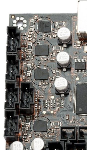
Well looking at the Einsy board it looks like there is enough room too fit heatsinks to the TMC8130 drivers to improve the cooling.
Regards,
Martin
Martin Wolfe
Re: Fine Vertical Artifacts / Trinamic Chop Tuning, Any Effect?
Probably using your oscilloscope to look at current & voltage levels to the motors after any changes - before any long print run would be advisable. Gotta admit, I'm having a hard time understanding exactly what "knobs" control stealth mode.
Also, the heatsinks should go on the bottom of the board, because the heatsink pad on the chip is on the bottom of the chip & soldered to a bunch of via's. Supposed to make the ground plane of the board a heatsink. Heatsinks on the top of the chips will be much less effective.
Lido 0.9 degree motors stealth vs stock
Definitely going to take some more work.
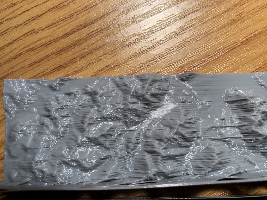
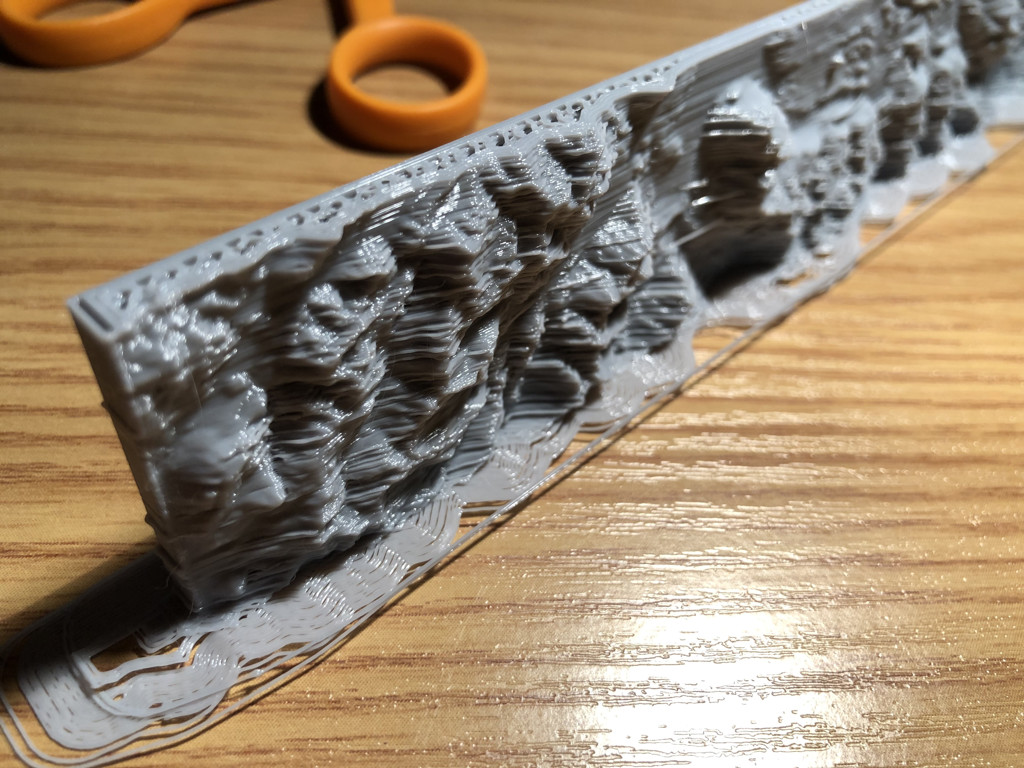
First, this is why I really want to get the 0.9's working. These two prints are a 3D topographic. Orientation for printing was standing on edge aligned with y-axis.


You can see that the 0.9's attenuate the VFA's. The print is much cleaner.
I already mentioned the overheat problem in stealth mode. I'll work on that later.
For today, I test with standard mode
Leaving run current levels unchanged (16, 16) for x and y
I got
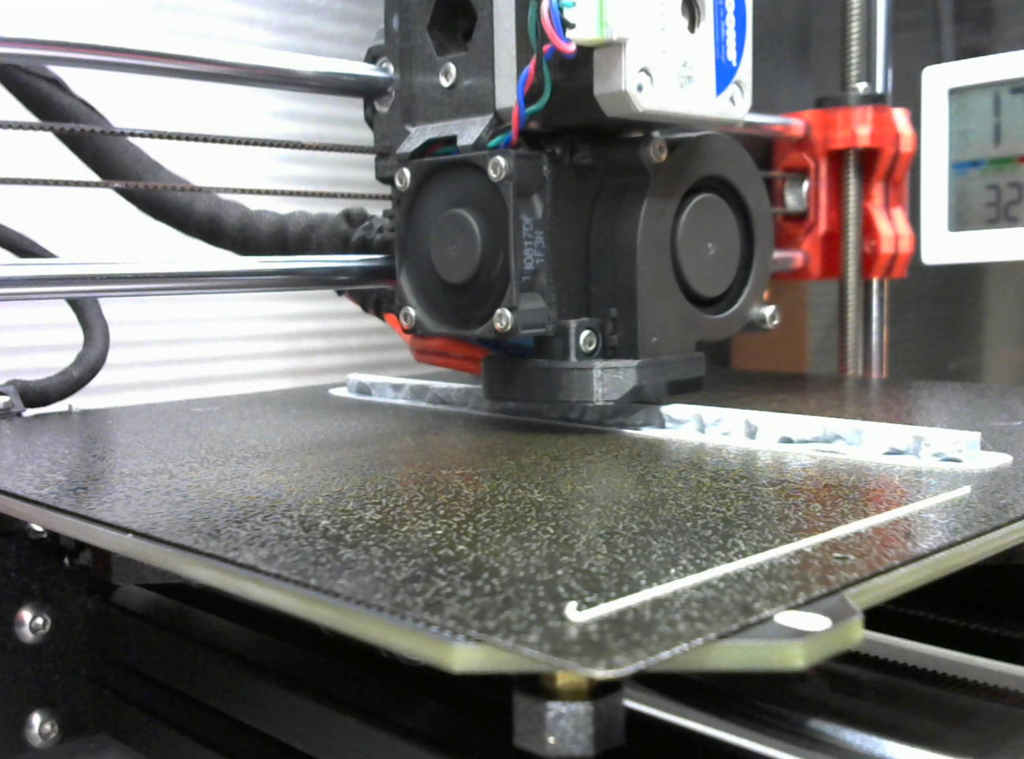
It was pretty ugly. At first I thought it was simply too little current. So I tried with currents at 28, 31, and 40.
I expected prints to improve with more current and torque, but instead it got worse. Progressively, worse y-axis shift as run and hold currents increased.
Re: Fine Vertical Artifacts / Trinamic Chop Tuning, Any Effect?
Looking at the first, messed up standard mode print, I realized that this might actually be the EINSY not being able to keep up with the demanded micro steps and skipping to steps. That would explain the straight line trajectories that skip intermediate positions.
I'm now testing with XY reduced to 8 micro steps, interpolation on, just like you proposed earlier.
Had to adjust steps resolution back down to 100 to get geometry back to normal.
Printer is a bit noisier, but the print is looking good thus far. Will know after more of the topographic is printed. I don't see any layer shifting or skipped over segments yet.
Still need to go back and tune the hysteresis to reduce noise, but for now I just want to see if I can get standard mode printing cleanly.
If the EINSY is indeed unable to keep up in standard mode with 0.9 steppers and 16 micro steps but is okay with 8 micro steps, I don't understand why it is works fine in stealth mode with 16 micro steps (other than the heat problem)
I have adjusted firmware to try reducing stealth mode current. Will test that later. If heat is still an issue, I think I can add a cooling fan to the EINSY case for the back side of PC board.
Re: Fine Vertical Artifacts / Trinamic Chop Tuning, Any Effect?
Confirmed. Running the LDO 0.9's in standard mode works if microsteps are adjusted down to 8 instead of 16.
Surface finish and geometry look great after printing 1/2 strip from topology map.
I also realize that my Y currents are at 16 (lower than the stock 20). I forgot I had turned it down weeks ago during some other testing. Leaving it at 16 until next fimware flash.
Now trying a full 12 hour print in standard mode.
Re: Fine Vertical Artifacts / Trinamic Chop Tuning, Any Effect?
Running the LDO 0.9's in standard mode works if microsteps are adjusted down to 8 instead of 16.
Just for my understanding: Doesn't going from 16 to 8 microsteps defeat the purpose of going from 1.8 to 0.9 °?
Re: Fine Vertical Artifacts / Trinamic Chop Tuning, Any Effect?
Doesn't going from 16 to 8 microsteps defeat the purpose of going from 1.8 to 0.9 °?
No. We weren't actually getting more print resolution with 400 * 16 microsteps addressable/revolution. The 0.4 mm nozzle is too large for the additional positions to make a resolution difference. The improvement is in monotonicity of the steps. Dropping back down to 400 * 8 microsteps/revolution is same addressable resolution as standard configuration, but with physically monotonic step positions. End result is same resolution, but much cleaner - essentially free of VFA's. My test strip came out as clean and sharp as when running with 16 microsteps in stealth.
In other words, the stock 1.8º motor configuration is 200 x 16 addressable microsteps but cannot actually achieve all those 3200 positions due to motor non-monotonicity. Hence, we got VFA's.
The LDO 0.9º motors in 8 microsteps have 400 x 8 addressable microsteps, but CAN actually hit those 3200 positions and we get rid of the VFA's without losing any print resolution.
Asking the EINSY to deal with 6400 positions was too much for the CPU to handle in standard mode. It somehow can in stealth mode, but I don't yet understand why.
Also, the Trinamic driver has interpolation on. That further smooths motion between the microsteps. It's almost like using a higher microstep value for motion, but without the CPU load of additional steps. You can't address the microsteps in between, but the driver chip uses them to smooth motion.
About six hours into a standard mode test print now. Still looking good.

Re: Fine Vertical Artifacts / Trinamic Chop Tuning, Any Effect?
The results you are achiving with the 0.9° steppers are looking amazingly clean. Thank you verry much for testing and sharing your results.
Now I wonder if the improvement in quality is simply due to the 0.9° step angle and therefore doubling the physical steps per revolution.
Out of curiosity I hope edgar.s2 is getting the 1.8° LDO steppers. That would complete the different motor variants.
1.8° would be an easier swap I guess. But looking at the quality of the 0.9° steppers ... if this is only achiveable with 0.9° steppers, I think the extra effort is worth it.
Damn I wish I could work on my printer at the moment and help testing. Those clean prints make me jealous. Thats the quality I ever wanted from the MK3.
Re: Fine Vertical Artifacts / Trinamic Chop Tuning, Any Effect?
If the EINSY is indeed unable to keep up in standard mode with 0.9 steppers and 16 micro steps but is okay with 8 micro steps, I don't understand why it is works fine in stealth mode with 16 micro steps (other than the heat problem)
Weird, indeed. I would guess that StealthChop is maybe better in ignoring irregularities in step frequency as compared to SpreadCycle, because StealthChop controls the current somewhat more indirectly.
As far as the overheating problem is concerned, I am afraid there is not much you can do about it. At higher speeds (or not so high speeds for 0.9° motors), StealthChop will always go full throttle and the only thing keeping the current from going through the roof is back EMF. There is actually a critical speed for overheating. Below this critical speed, StealthChop will actually down-regulate the current; above the critical speed, backEMF will be the limiting factor and reduce the current as the motor goes faster - that's at least my take on it. So when checking whether the TMC drivers can take it, you should check at different speeds. Or stick to SpreadCycle, which is anyway the safer option when it comes to layer shifts.
As bad as this high-current motor might work with StealthChop, as good it might work with SpreadCycle, but that is just a guess. Unfortunately, I still haven't developed a good intuition about motors. There seem to be always more variables to be taken into account than fit into my working memory.
Re: Fine Vertical Artifacts / Trinamic Chop Tuning, Any Effect?
I think this is all great progress. I was also worried about the einsy keeping up with the step rate. I Did more study on stealth mode.
I am currently looking more closely at chapter 6.2.1 Lower Current Limit(pages 41, 42). it starts with "The stealthChop current regulator imposes a lower limit for motor current regulation.". It also states "The run current setting needs to be kept above the lower limit" then goes on to describe how to calculate this.
When I try plugging the values from the firmware (TBL=2, pwm_freq=2) and your motor's coil resistance of 1.65 ohms - I come up with a lower limit of just over 2 amps! I then tried the calculations with the stock motor resistance of 6.5 - it still comes out to .519 amps, or a setting of 30 but the standard setting is only 20 for the Y & 16 for the X(same motor). In the case of the X motor - this is ~54% of the calculated value.
Very puzzling - but at the end of the section, it has a note stating "For pwm_autoscale mode, a lower coil current limit applies. This limit can be calculated or measured using a current probe. Keep the motor run-current setting IRUN well above this lower current limit." Now we are using pwm_autoscale mode, so I guess this applies - but it doesn't give any more hints about how to calculate the lower limit value for pwm_autoscale mode.
If I change pwm_freq to 1(35.1kHz) and TBL to 0(16 clocks, ~1.3microsec), I get a lower run current limit of .68 amps(44), but if I scale it to the same 54% as the X stock motor it comes to .381 amps(22).
If I set TBL to 1(24 clocks) and pwm_freq to 1(35.1kHz) and use the same scaling - I get .54 amps(34)
So, I think that you may need to change both pwm_freq to 1 and TB L to 0 or 1 - then try using run currents in the 22 to 36 range(and of course break out your trusty o'scope 😀 ).
Re: Fine Vertical Artifacts / Trinamic Chop Tuning, Any Effect?
I am so happy not to be working on this alone.
The standard mode print is still going. It is looking very nice - probably among the best I have ever see translucent PETG coming off this printer.
The 0.9 degree motor is letting the printer to finally produce results that I envisioned as being produced by a printer with a reputation for superior quality. The MK3 stock performance was a bit disappointing. Now we are on the brink of getting the print results we want.
Between us all working away, we'll get both standard and stealth modes worked out for the 0.9's
I occurs to me that someone should also try 8 micro steps with the stock motors. That will drop the resolution, but would be interesting to know if that changes the VFA's
Re: Fine Vertical Artifacts / Trinamic Chop Tuning, Any Effect?
I am so happy not to be working on this alone.
Me too. Wish I could do more, faster. I've been continuing to work on the linear correction wave generation & think that I'm close. I have been trying to get a modified sin^power working in a way that maintains constant torque.
Not really that difficult to generate, but tough(at least for me) to get them all (power values from .8 to 1.2) working with the 2130's compression scheme. I think they need to add at least 2 more segments or, preferably, make the table entries 3 bits - allowing -3 to 3 deltas, single segment. Oh well, that's not going to happen - so back to reality.
I have a very close fit in simulation(C code, but not in firmware), now I need to port it to the firmware without breaking anything.
@guy.k2, are you running 3.5.1 or 3.5.2? I'll put it in whichever you are using, since I'm not yet operational(but getting close).
Re: Fine Vertical Artifacts / Trinamic Chop Tuning, Any Effect?
Still on 3.5.1
Watching bug reports for a while before making the switch.
Re: Fine Vertical Artifacts / Trinamic Chop Tuning, Any Effect?
I have been trying to get a modified sin^power working in a way that maintains constant torque.
How can you tell if constant torque is maintained? Also, I wonder how much the optimal curve would change with speed.
Re: Fine Vertical Artifacts / Trinamic Chop Tuning, Any Effect?
After some digging, I believe that for a 2 phase stepper the stator torque is sqrt(phaseA^2+phaseB^2), where phaseA and phaseB represent the current in each phase(phaseB is the wave, offset by 90 degrees). So for example, if the amplitude of the TMC2130 "Wave" is 247, then the stator torque for all 256 microsteps should be 247. for purposes of generating the wave(since it's not dynamically re-computed) speed is not relevant. Maintaining constant torque generates the smoothest motor movement.
A pure sine wave generates this condition naturally, but once you start adjusting it, you need to pay attention to making sure that the adjusted wave still maintains the constant torque and no big discontinuities in the wave. I'll post some graphs and better description soon.
Once the speed becomes too high for the wave to be maintained, switching to full step drive should occur(not sure yet, if the TMC2130 does this).
Re: Fine Vertical Artifacts / Trinamic Chop Tuning, Any Effect?
After some digging, I believe that for a 2 phase stepper the stator torque is sqrt(phaseA^2+phaseB^2), where phaseA and phaseB represent the current in each phase(phaseB is the wave, offset by 90 degrees).
Yes, theoretically. But one of the benefits of having a programmable wave is to compensate for torque deviations in a real motor. Since it is rather difficult to measure torque behavior at microstep resolution while the motor is spinning, I was wondering whether a wave that was optimized for the static case would also be beneficial at normal printing speeds (and possibly different loads). Well, might not be worth the trouble anyway, if affordable motors do the trick without fancy wave optimization.
Re: Fine Vertical Artifacts / Trinamic Chop Tuning, Any Effect?
Very puzzling - but at the end of the section, it has a note stating "For pwm_autoscale mode, a lower coil current limit applies. This limit can be calculated or measured using a current probe. Keep the motor run-current setting IRUN well above this lower current limit." Now we are using pwm_autoscale mode, so I guess this applies - but it doesn't give any more hints about how to calculate the lower limit value for pwm_autoscale mode.
Yes, confusing. I guess the note is just referring to what was described before. I read the "a lower coil limit applies" as "THIS lower coil limit applies", because the text above clearly refers to automatic mode. In non-automatic mode, current is not measured anyway and so the problem of the ON phase being too short for measuring the current does not exist.
I agree that the Prusa settings are sub-optimal, to say the least, and might be the cause for layer shifts under special circumstances. I am using TBL=1 (24 cycles) with pwm_freq=1 (35kHz), with the stock motors.
Re: Fine Vertical Artifacts / Trinamic Chop Tuning, Any Effect?
@Dreide
Yes, theoretically. But one of the benefits of having a programmable wave is to compensate for torque deviations in a real motor.
What we're trying to correct are position errors, not torque errors per se(though they might be related). but varying the wave from a pure sin wave varies the relative torque between phaseA & phaseB, which shifts the position, while maintaining the same total stator torque.
I read the "a lower coil limit applies" as "THIS lower coil limit applies"
I initially thought the same, but when you plug in the numbers for the firmware settings and the stock motor - the results are not even close. That plus the fact that they placed this note AFTER describing the equations and previously warning to keep IRUN above the calculated limit, leads me to believe as I stated. Of course I could be totally wrong.
Re: Fine Vertical Artifacts / Trinamic Chop Tuning, Any Effect?
Not quite done working on it yet, but here's a graph showing what I think is happening & what I'm trying to do:

The solid black line is a pure sine wave. It generates constant torque,shown by the "Max Torque Allowed" line, through all 256 microsteps.
The sin raised to a power(1.2 in this example) is shown by the red dotted line"Raw Sin^Power". This is what the Prusa implementation does. If you notice, the torque generated by this curve, which is the "RawSin^PowerTorque" red dotted line, along the top of the chart - is ok near each end, but droops in the middle.
The green dotted lines show the sin raised to the same power, but adjusted to maintain constant torque. The concept is pretty simple. During the 128 steps of the cycle, it is just the sin raised to the power - but scaled so that it reaches the correct midpoint. This is necessary to prevent a discontinuity in the wave at the midpoint. The remaining 128 steps are calculated so that the square root of the sum of the squares of the symmetrical pairs equals the amplitude(247 in this case) - e.g. point 128 is paired with point 127, point 129 is paired with point 126.... point 0 is paired with point 255. If the selected correction factor is zero(giving a power of 1), this technique generates a correct pure sine wave.
I don't know if it will really improve the performance, and because of rounding induced errors and being able to generate the matching curve with the TMC2130's compression scheme - it isn't perfect but currently the torque doesn't vary by more than 2 counts(out of 248). Still trying to improve this.
Anyway, I'm new to this, so if any of you are more knowledgeable(highly likely) and want to share your views on why I might be going down the wrong path - please chime in 🙂
ps - the chart title says fac1000=100 & power = 1.2. This is because I am using fac1000 as a signed number & multiplying it by .002 instead of .001, which allows the power to go from .744 to 1.27 more or less. this was so it could still fit in the 8-bit value stored in flash.