View Mesh Bed Leveling Data
I notice that on prints that take up a large portion of the bed, I can see my z-axis making a fairly significant correction. Is there a G-code that returns the exact offsets mesh bed leveling calculates? It would be nice to view the grid values so I know where to massage the frame back into physical alignment. XYZ Calibration details don't give you the information.
Re: View Mesh Bed Leveling Data
G80
G81
Re: View Mesh Bed Leveling Data
G80
G81
Love ya!
Re: View Mesh Bed Leveling Data
Ok question 2. How do I interpret it? It measures nine points yet I get a whole lot more data back than I expected.
 -0.31500  -0.22028  -0.14944  -0.10250  -0.07944  -0.08028  -0.10500

  -0.21046  -0.12362  -0.06128  -0.02343  -0.01007  -0.02121  -0.05685

  -0.11713  -0.04091  0.01126  0.03935  0.04338  0.02335  -0.02074

  -0.03500  0.02787  0.06815  0.08583  0.08093  0.05343  0.00333

  0.03593  0.08271  0.10940  0.11602  0.10255  0.06900  0.01537

  0.09565  0.12360  0.13502  0.12991  0.10826  0.07008  0.01537

  0.14417  0.15056  0.14500  0.12750  0.09806  0.05667  0.00333
Re: View Mesh Bed Leveling Data
I think it is this, based on the corrections that I did.
-.315 is the measurement on the back, left corner of the bed
.00333 is the front right of the bed.
You can check by putting a tiny bit of paper under the flexible steel sheet on that back corner and re-run, see if the number changes a lot.
Since the bed is NEAR you when you print on the back of the bed to correct this you could raise the left-side Y axis rod on the front of the machine. Perhaps remove the zip tie and put paper between the rod and the plastic block zip down and try again.
either that or check the Back of the left Y axis rod and see if it can be tightened down further - is the zip tie totally tight?
I'm reading through the code now but it is a lot more involved than I thought. There seems to be interpolation that fills in these other points, but still doesn't make 100% sense yet.
Re: View Mesh Bed Leveling Data
Yeah some values are direct measurements and some in between are interpolated. If I remember correctly
Re: View Mesh Bed Leveling Data
Measured values are on line 1, line 4 and line 7. They are the 1st, 4th and 7th values on each line. The rest of the table is filled by interpolation between these nine measurements.
Re: View Mesh Bed Leveling Data
Measured values are on line 1, line 4 and line 7. They are the 1st, 4th and 7th values on each line. The rest of the table is filled by interpolation between these nine measurements.
Nice. this makes more sense.
Re: View Mesh Bed Leveling Data
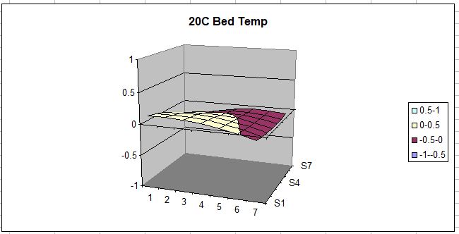
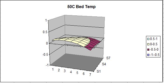
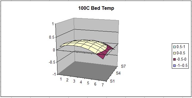
Note that the temperature of the bed has a large influence on these numbers.
Take a look at these graphs, with the Bed at 20, 50, and 100 degrees C:
Re: View Mesh Bed Leveling Data
Note that the temperature of the bed has a large influence on these numbers.
Take a look at these graphs, with the Bed at 20, 50, and 100 degrees C:
yeah , apparently the pinda temp offsets don't really work as advestised.
look here, as well as the previous thread linked in the first post:
https://shop.prusa3d.com/forum/original-prusa-i3-mk3-f30/1st-layer-problems-in-depth-look-at-software-pinda-t14815.html
Re: View Mesh Bed Leveling Data
I can't leap to any conclusion regarding the Pinda calibration info- it could very well be that the numbers spit out with the G81 command are PRE-correction. I've not looked into the code yet to determine this. What I do know is that I don't have the Z-height problems that others have complained about here- mine is very consistent.
Re: View Mesh Bed Leveling Data
http://lokspace.eu/3d-printer-auto-bed-leveling-mesh-visualizer/
Try this site. It will visualize levels on your bed.
Re: View Mesh Bed Leveling Data
..... yeah , apparently the pinda temp offsets don't really work as advestised. .....
This is showing that the bed changes shape with thermal expansion. In order to verify the Pinda height sensor one would have to compare the height measured with feeler gages. The Pinda is probably reporting the bed height just as it is.
When I checked the mesh leveling and adjusted one corner the end result is that I had symmetry but the center was still higher than the outsides. The difference is very small. I considered the idea of shortening the center spacer to compensate or putting shims under all of the other spacers except the middle one. However, since this slight crown never affects my prints I just left it.
I should have clarified: there was discussion in the previous thread about exactly that, several of us including myself have been shimming the standoffs to correct the bed level. support has said before that > .2 difference is not ideal and won't be compensated as well. Obviously the bed will expand but the larger issue is that the probe isn't compensating like it should be when it does expand or change. The temp calibration of the probe itself is the obvious suspect.
Re: View Mesh Bed Leveling Data
The results you get from the mesh level report are meant to feed the software during printing. One might say these are pre-compensation. The Pinda senses it's own temperature in order to measure distance correctly. If you want to find if it is doing the job you need to use feeler gages. Pinda is not supposed to adjust directly for different bed temperature but it's results will help the printer indirectly account for this.
I think it is like this.
1. heats the bed
2. measure the distance(s) between the E-axis and the bed (using a temperature compensated height sensor)
3. interpolate the distances to create offsets to follow (either lookup tables or or formulas to follow during printing)
4. print with offsets calculated in (3).
if the bed is warped, the measurements will show the warp and the Z axis will help to follow those (very slight) contours.
btw, I have not noticed any problems except 1, that my printer as built had one low corner and I raised this with a custom y-axis rod holder. I have only printed PLA and PC-MAX so far and I have only printed parts that are up to about 80% of the bed width.