Spare pins/pin diagram for EINSY miniRAMBo board?
I've got a burning desire to make my Prusa have LED lights that sync to various print states. Yeah, it'll probably be ugly. I don't care. I'm gonna do it anyway 😀
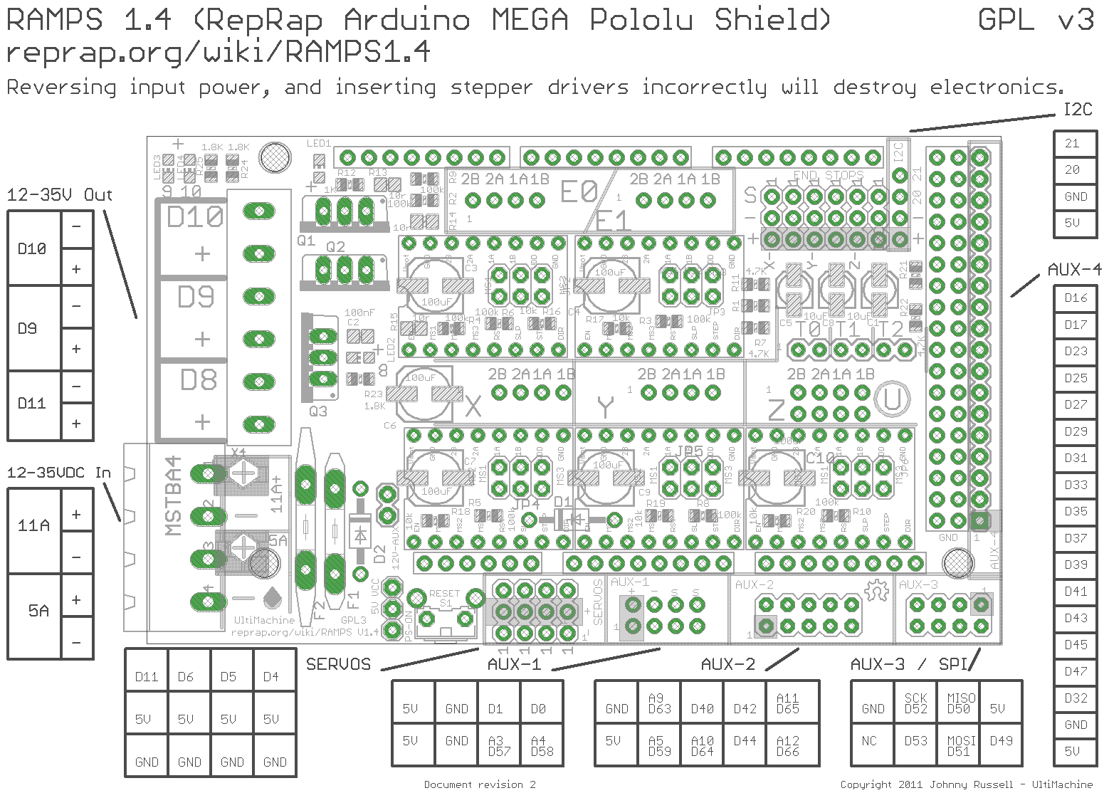
Is anyone aware of a pin diagram for the EINSY miniRAMBo board that would show whether there are any gcode addressable spare pins that could be used to control the LED lights? I'm looking for something like this:
Re: Spare pins/pin diagram for EINSY miniRAMBo board?
I found a post about this for the MK2 ( https://shop.prusa3d.com/forum/original-prusa-i3-mk2-f23/mk2-rambo-pin-available-for-led-control-w-gcode--t5071.html ) and am basically wondering if anything's changed with the new board in the MK3.
Re: Spare pins/pin diagram for EINSY miniRAMBo board?
Did you ever find a diagram?
Re: Spare pins/pin diagram for EINSY miniRAMBo board?
Should be here: http://reprap.org/wiki/EinsyRambo but the site seems to be down right now.
Here's a schematic too: https://github.com/ultimachine/Einsy-Rambo/blob/0.5a/board/Project%20Outputs%20for%20Einsy_Rambo_0.5c/Schematic%20Prints.PDF
There are other forks on the github if you have a different version than the 0.5c, but I think that's what most people have at this point.
Re: Spare pins/pin diagram for EINSY miniRAMBo board?
I've actually given up on this approach. Instead I'm going to take advantage of a plugin for OctoPrint that intercepts M commands for controlling LEDs and sends them out the Raspberry Pi GPIO pins instead.
I've 75% finished a little board that will connect to the GPIO header on my Pi B+ that runs octoprint, and that board connects to the LEDs. I'll just insert gcode from S3D for the light states I want, OctoPrint will intercept those, and will send the appropriate signal out the GPIO.
No need to screw around with the miniRAMBo at all.
Once it's done I'll post pics and stuff.
Re: Spare pins/pin diagram for EINSY miniRAMBo board?
Hey, has anyone found more info on this? I'm trying to do the same thing!
Re: Spare pins/pin diagram for EINSY miniRAMBo board?
Hey, has anyone found more info on this? I'm trying to do the same thing!
See my post above yours. There's no point to trying to tie into the EINSY board. Instead run Octoprint on a Raspberry Pi B+, make your own MOSFET board/Pi Hat, and drive the lights via Octoprint.
Re: Spare pins/pin diagram for EINSY miniRAMBo board?
hey Neil, could you elaborate at all on how you got this working? im expecting my printer within a week, and i have my pi 3b+, rgb leds, mosfets, buck converter (was planning on stealing power from the PSU), all ready to go, but this is my first time with a 3d printer, or a rpi, so i literally have 0 experience with any of this. any information would be helpful!