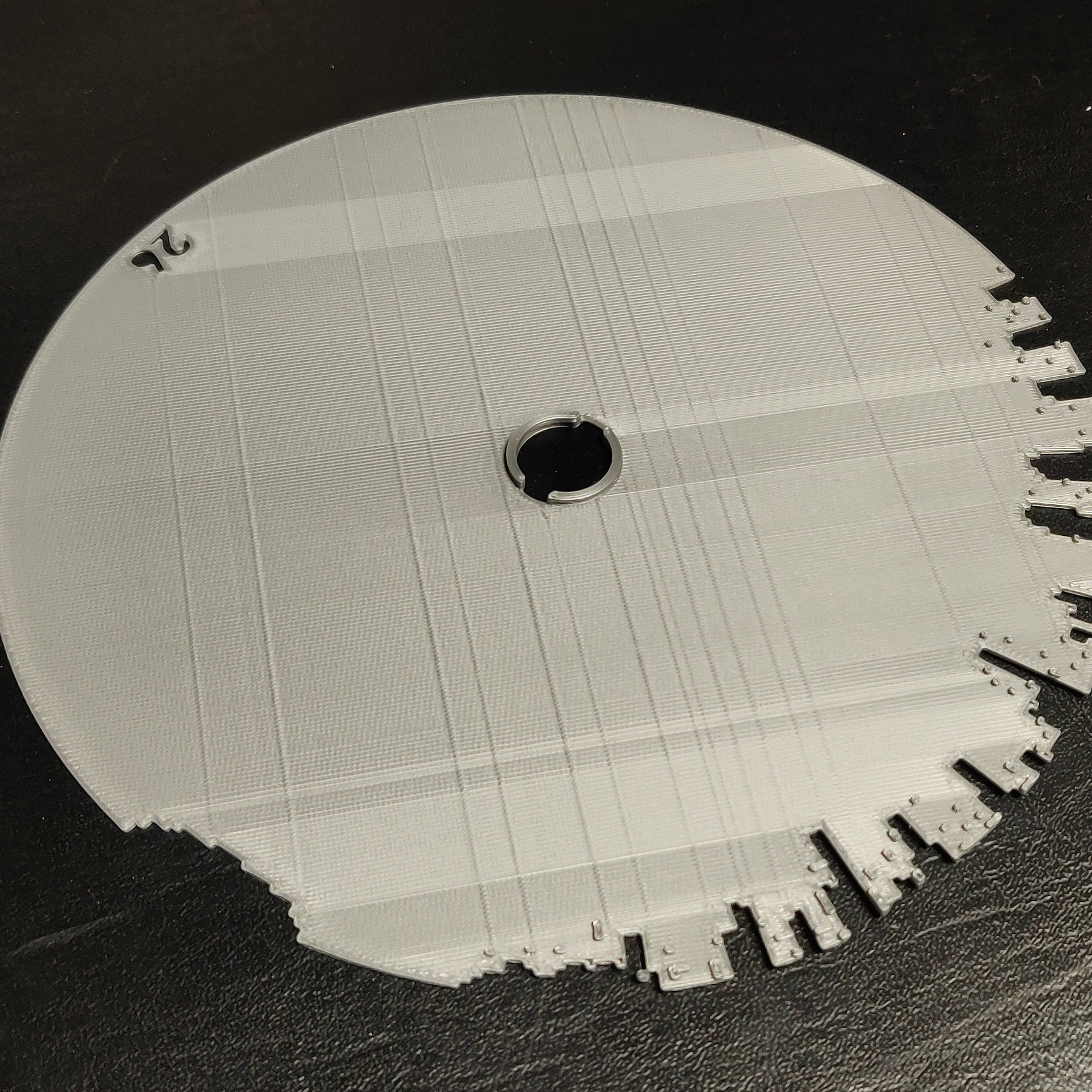
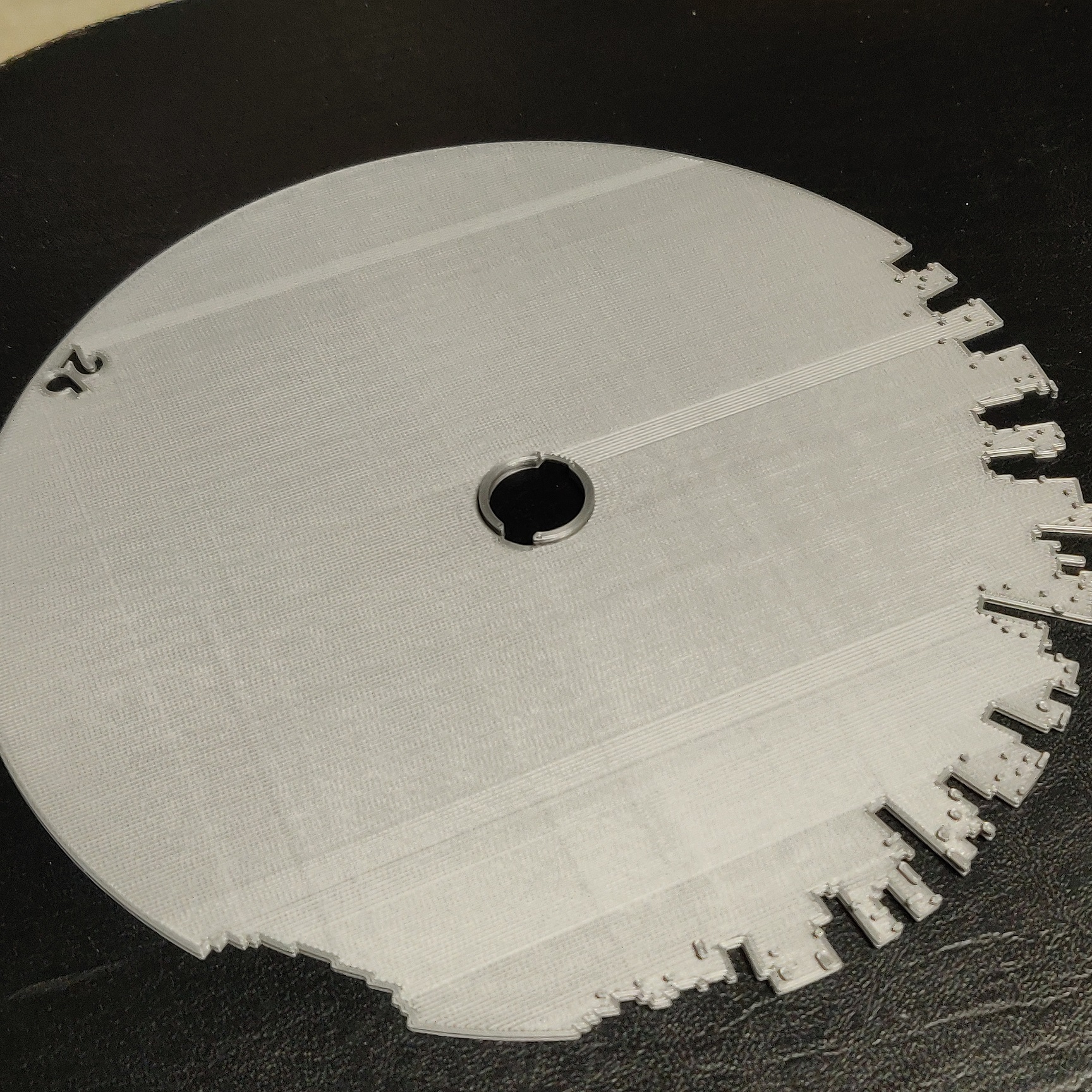
Surface lines
I read tons about under/over extrusion, line width and extrusion multiplier. I tested multiple settings, see attached. At 0.9 extrusion multiplier, I get a much nicer finish, but I still see lines. The lines are generated on solid infill and top solid infill. These are all 100% infill by the way, so the number of bottom and top layers doesn't count; they're all solid infill.
The lines are created when the printer prints solid infill, stop and move the nozzle to a different location on the same layer to do another section of the infill, and comes back where it left up. Although less pronunced at 0.9 then 1.0, this movement still creates the lines, whether it's on the X or Y axis.
Slic3r PE 1.41.3+win64
Printer Settings: Original Prusa i3 MK3
Print Settings: 0.20mm MK3 modified (solid infill at 100mm/s, solid infill width 0.4mm, tried 0.3mm, tried 0.45mm, etc..)
Filament Settings: Prusa PLA (1.0/0.9)
Filament: AmazonBasics PLA Silver
Would appreciate some tips please, thank you much.
Re: Surface lines
There is another thread on this same topic. I stopped reading it because lots of ideas but no solutions - except - slowing down infill feedrate helps a lot.
There seems to be a defect in the firmware that doesn't properly compensate for offset or position when the slice changes directions. Printing slower allows the nozzle to "iron out" some of the imperfection, and may even prevent some of the offset in the first place.
Increasing belt tension may also help (at least ensure tension is adequate).
Re: Surface lines
> There seems to be a defect in the firmware that doesn't properly compensate for offset or position when the slice changes directions.
Really?
> Printing slower allows the nozzle to "iron out" some of the imperfection, and may even prevent some of the offset in the first place.
I believe it is just physics. The molten plastic has quite a low viscosity, so if you print quickly, it will flow differently than if you print slowly and you give the low viscosity filament time to flow into the gaps towards the neighboring extrusion. It has nothing to do with the firmware.
Re: Surface lines
> Printing slower allows the nozzle to "iron out" some of the imperfection, and may even prevent some of the offset in the first place.
I believe it is just physics. The molten plastic has quite a low viscosity, so if you print quickly, it will flow differently than if you print slowly and you give the low viscosity filament time to flow into the gaps towards the neighboring extrusion. It has nothing to do with the firmware.
That might be true if when printing from one direction the part had the same artifacts. The effect only shows up when the printer turns around and infills back to an already filled location. At the 'collision point' there is too much plastic extruded for the volume and a thick line is formed. Higher temps do not alleviate the issue.
If the printer infills several sections, all from the same direction, e.g., left-right, there is no thick line. If the printer infills sections and two fields meet from both directions, e.g., one is filled right-left, the other left-right, you will see a thick line.
ps: I've explored this a bit, and it isn't a slice issue. I'm beginning to believe the TMC microstep table being used is partly to blame. There are certain drive conditions that cause a position error of several microsteps. The step appears related to absolute position, planned direction of motion, and accelerations. And it is very repeatable. While it might be a red herring, there seems to be correlation.
Re: Surface lines
I've noticed this and it's quite annoying. The lines are clearly different as though they are slightly different extrusion widths or something, giving them a clearly defined change in colour.
Re: Surface lines
The directional texture difference is - by my guess - two things: 1) is the nozzle has different scratches on the flat; it might help if it were polished and perfectly parallel to the bed; 2) acceleration is different depending on starting and ending point, and ringing artifacts no longer align.
You can reduce the second by slowing things down. But you have to go painfully slow, and you never get rid of all of the texture. It is also material dependent: nice opaque matte colors like white and beige show the effect less. Glossy materials highlight it.
Re: Surface lines
If the printer infills several sections, all from the same direction, e.g., left-right, there is no thick line. If the printer infills sections and two fields meet from both directions, e.g., one is filled right-left, the other left-right, you will see a thick line.
Thanks tim.m30 for your replies. This is by far the best description of the issue. I will continue doing test prints.