Concave walls bent
I have a mk3s and a mini+
im printing PETG
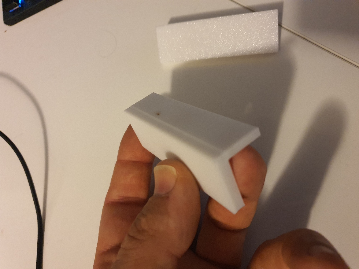
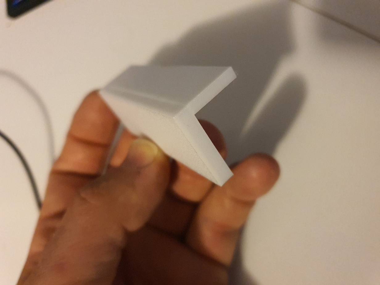
this is only a new problem and only happens with a part that has a L shape
it happens on my mini+ and my mk3s
the mini is new but i have had the mk3s for 2 years now and i have not had this problem before
I have been using the same petg since 2018
if i print a thin vertical object its fine it only happens when there is a change L shape like the photo
any help would be amazing
im printing at 240/80
cheers
Bryan

Im having issues with my printer
RE: Concave walls bent
just a suggestion, I don't have much information to go on.
possibly a cooling issue, look at the part orientation on the bed relative to the cooling fan, and possibly Adjusting the amount of cooling for that portion of the print if reorienting doesn't do the trick.
The Filament Whisperer
RE: Concave walls bent
A pity you said concave. If it were convex I'd say, it's the well-known bulge issue (search for the misspelling "buldge", and you'll find 16 pages of discussion).
What's your print orientation? Do you have the large flat part down and then print the smaller leg of the L upward? What happen if you put the smaller part down? Or if you turn the whole thing 90 degrees around so that the L shape is on the bed and then print it upward along the long axis?
RE: Concave walls bent
@swiss_cheese
Cooling was at 30 / 50
I have tried increasing the cooling to 70/100
The part is only a mock up of an other model
And I need to print this way.
Not looking at putting it on its end.
RE: Concave walls bent
@bryan
I wasn't suggesting putting the piece on it's end that was someone else, I was wondering what the orientation was on the bed from the X and Y axis stand point, when the printer cools, the material is doing more cooling from the front with the stock fan shroud then it does from the rear, it's not an even amount of cooling. orientation can help this in some cases. my suggestion is to orient the part on the Y axis and try for more even cooling along the edge that's giving you the trouble, if your not already doing that.
It's always more helpful when a person posts a zipped up .3MF project file because it shows us where possible mistakes are being made and helps to facilitate more effective communication about the project/problem being discussed.
The Filament Whisperer
RE: Concave walls bent
I was suggesting putting it on its end, not necessarily because that's the best position but to see if the artifacts remain in the same place.
RE: Concave walls bent
A pity you said concave. If it were convex I'd say, it's the well-known bulge issue (search for the misspelling "buldge", and you'll find 16 pages of discussion).
It very likely is the same issue. It happens when there is a transition internally, typically a transition from sparse to solid infill, or enabling gap fill.
What's your print orientation? Do you have the large flat part down and then print the smaller leg of the L upward? What happen if you put the smaller part down? Or if you turn the whole thing 90 degrees around so that the L shape is on the bed and then print it upward along the long axis?
If I'm understanding the original post, it's being printed with the wider leg flat and the ridge is occurring on the vertical wall where it transitions from sparse to solid infill.
@Bryan - if you want to investigate this yourself, here's the info dump:
-
From solid infill to sparse
-
From sparse infill to gap fill
-
Be sure you're not just seeing the effect of minor warping. This can really throw troubleshooting off. Rotate the print and verify the problem occurs in the same place.
-
Slow down external perimeter speeds (and all speeds in general). If the nozzle is moving a bit too fast, you get slight under extrusion on some layers. These are apparent as adjacent layers print with slightly different extrusion rates. I use 25mm/s for external perimeters when appearance is important.
-
Calibrate your extrusion multiplier for each filament. Any slight over or under extrusion can produce very small but noticeable variations in layers with different features (e.g. infill, gap fill, top solid infill). The closer your slicer settings match your actual printer and filament, the more accurate the gcode will be.
-
Calibrate linear advance (LA) for each filament. LA adjusts the flow of filament to compensate for acceleration and deceleration. If it's not right, you may see artifacts even away from features such as bumps or hole on the same layer. In some cases, a hole on one wall causes imperfections on the far side of the print.
-
Add an external perimeter if vertical walls allow it. The thicker combined perimeter allows the filament flow to even out. Increase or decrease number of perimeters. You're trying to make the transition less dramatic, and specifics will vary by part.
-
Tweak perimeter extrusion widths. The problem can appear when the slicer switches between gap fill, sparse infill, and solid or top infill. If you can find a multiple of perimeter widths that minimizes these transitions, it can work for a specific print.
-
If you are the part designer, make vertical free-standing walls thicker. IME, at 1.5mm thick, the problem is less noticeable. You can try for a multiple of extrusion widths, although be aware the PrusaSlicer does some internal calculations for overlap between extrusions that can throw you off.