Re: Any ideas how to get this flexable material to print?
I something was stuck inside the nozzle. I tried everything from heating it to 300C and using a acupuncture needle to tweezers. But all i got was a small hole but not the 0.4mm. Then I used a 0.4mm drill bit and that did this:

[/quote]
Last night after refitting the PTFE tube and reshaping it to fit I started to experience a clogged nozzle when testing flex again. The only thing I can think of is that a small piece of PTFE must have gone down the tube and started to clog the nozzle. Luckily I was able to heat up real hot and then use an acupuncture needle to free it. Something for others to be aware of when they are trying to shape their piece of PTFE tube.
On another note I found that I was able to print with this new setup TPE up to speeds of 30mm/s (I think 85a) successfully. I needed to print some harder tpu 98a and found that I cannot print this reliably yet. I have tried speeds down to 15mm/s before I found the clog. I think it may print at 15mm/s but very picky in what you can and cannot do with the bondtec setup. You have to be real precise on the gear pressure and the speed.
Re: Any ideas how to get this flexable material to print?
Sometimes you need to ask to find the answer! 
This is the bondtech gears that are not aligned, not really the body... I did not understood the view correctly...
Do you know where I can download the bondtech CAD files? I would like to do this for MK2.5 as well (x-carriage and x-carriage-back differ from MK3)
Here is the Bondech pully: https://www.dropbox.com/s/6kor4mngm41vznp/Bondtech%20Gears.stp?dl=0
or as stl: https://www.dropbox.com/s/m1j2lhimv5z8e27/pully1.stl?dl=0 and https://www.dropbox.com/s/mw6nabr9ye21irr/pully2.stl?dl=0
Last night after refitting the PTFE tube and reshaping it to fit I started to experience a clogged nozzle when testing flex again. The only thing I can think of is that a small piece of PTFE must have gone down the tube and started to clog the nozzle. Luckily I was able to heat up real hot and then use an acupuncture needle to free it. Something for others to be aware of when they are trying to shape their piece of PTFE tube.
On another note I found that I was able to print with this new setup TPE up to speeds of 30mm/s (I think 85a) successfully. I needed to print some harder tpu 98a and found that I cannot print this reliably yet. I have tried speeds down to 15mm/s before I found the clog. I think it may print at 15mm/s but very picky in what you can and cannot do with the bondtec setup. You have to be real precise on the gear pressure and the speed.
Jep I maybe had the same problem. I was sure that I looked if there is anything left inside the tube... but maybe... we will never know.
Sh** happens. But that is a really big pile of sh**. Hopefully my next will last longer.
Re: Any ideas how to get this flexable material to print?
Sometimes you need to ask to find the answer!
This is the bondtech gears that are not aligned, not really the body... I did not understood the view correctly...
Do you know where I can download the bondtech CAD files? I would like to do this for MK2.5 as well (x-carriage and x-carriage-back differ from MK3)
Here is the Bondech pully: https://www.dropbox.com/s/6kor4mngm41vznp/Bondtech%20Gears.stp?dl=0
or as stl: https://www.dropbox.com/s/m1j2lhimv5z8e27/pully1.stl?dl=0 and https://www.dropbox.com/s/mw6nabr9ye21irr/pully2.stl?dl=0
Thank you 😉
Re: Any ideas how to get this flexable material to print?
I've been successfully printing with TPU when suddenly I got jammed nozzle and filament coming out on the side of the extruder.
After a couple of tries I found that increasing the nozzle temperature from 240 degrees to 250 degrees did the trick.
The prints now looks better than ever.
Re: Any ideas how to get this flexable material to print?
see attached a section view picture that illustrates that. I have to test it out in detail to determine if it's close enough to the gears, but until now it seems to work fine. As mentioned, time will tell. I'll send you the files, use them as you like, totally fine with me 😉
I really like this idea! Will you be ok to share this dimension?
I am currently taking the hard way by doing everything from scratch under Fusion 360. This gives me more flexibilities to add/remove few details. I will share when finished 😉
Re: Any ideas how to get this flexable material to print?
I really like this idea! Will you be ok to share this dimension?
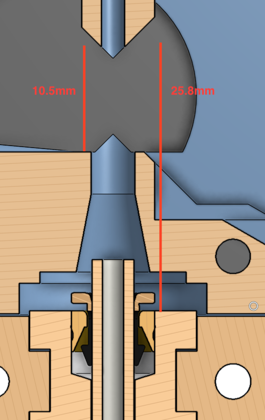
According to the model this should be 10,5mm.
Sorry for not being in touch for a time, but i had a lot of stuff to do and print...therefore i have an update to the Flexible extruder...
After some time my extruder started to fail. Turn out the idler is the one to blame. I switched to the original Idler and it worked very well. Seems like i have miscalculated some measurements. The idler didn't go in far enough, so the bondtec gears had a chance to slip. And that happened because the gear of the idler side caught up with the idler itself.
After a lot of prints, and about 60 hours of perfectly fine printed TPE at 30mm/s I had a serious Spaghetti incident. I observed the system, and the weak spot is always the same. The grove of the gears do form a natural gap. Additionally I was a little bit to shy to get closer to the gears themselves with the Filament inlet, so it formed an even larger gap. Slightly misalinged gears and a little bit to much tension on the idler springs resulted in failure of the print. Although the system basically works if everything is set properly, it's not reliable enough for my needs. Attached is a picture of the hopefully improved design. I'm printing it right now, so let's see how things turn out. It's now the 4th revision of the 2nd Version.
I'm planning to go one step further. I want to alter the motor mount position in the printers Y-Axis and the idler design, to be able to flip the bondetc gears, so the gear side faces towards the stepper. Then I would be able to mount a counter bearing on the steppers shaft. I really want to take those radial loads of the stepper and fasten it's position, although the stepper shaft is normally already equipped with two bearings, i don't like the fact that the gear is mounted on the outermost position of the shaft. Please let me know what you'd think about that.
(Sorry for the "semi professional" Picture editing)
Re: Any ideas how to get this flexable material to print?
I really like this idea! Will you be ok to share this dimension?
According to the model this should be 10,5mm.
Sorry for not being in touch for a time, but i had a lot of stuff to do and print...therefore i have an update to the Flexible extruder...
After some time my extruder started to fail. Turn out the idler is the one to blame. I switched to the original Idler and it worked very well. Seems like i have miscalculated some measurements. The idler didn't go in far enough, so the bondtec gears had a chance to slip. And that happened because the gear of the idler side caught up with the idler itself.
After a lot of prints, and about 60 hours of perfectly fine printed TPE at 30mm/s I had a serious Spaghetti incident. I observed the system, and the weak spot is always the same. The grove of the gears do form a natural gap. Additionally I was a little bit to shy to get closer to the gears themselves with the Filament inlet, so it formed an even larger gap. Slightly misalinged gears and a little bit to much tension on the idler springs resulted in failure of the print. Although the system basically works if everything is set properly, it's not reliable enough for my needs. Attached is a picture of the hopefully improved design. I'm printing it right now, so let's see how things turn out. It's now the 4th revision of the 2nd Version.
I'm planning to go one step further. I want to alter the motor mount position in the printers Y-Axis and the idler design, to be able to flip the bondetc gears, so the gear side faces towards the stepper. Then I would be able to mount a counter bearing on the steppers shaft. I really want to take those radial loads of the stepper and fasten it's position, although the stepper shaft is normally already equipped with two bearings, i don't like the fact that the gear is mounted on the outermost position of the shaft. Please let me know what you'd think about that.
(Sorry for the "semi professional" Picture editing)
Thank you Petehagoras!
Your point is interesting. Did you move the E motor by 0.5 or 0.4mm? Like is it really 9mm between two gears or a bit more?
Or more globally, does Bondtech produce an implementation guide for their gears (I could not find this but this should exists somewhere)?
Re: Any ideas how to get this flexable material to print?
If you guys don't mind, what/whos brand of PETG are people using thats available for purchase in USA?
Re: Any ideas how to get this flexable material to print?
Thank you Petehagoras!
Your point is interesting. Did you move the E motor by 0.5 or 0.4mm? Like is it really 9mm between two gears or a bit more?
Or more globally, does Bondtech produce an implementation guide for their gears (I could not find this but this should exists somewhere)?
I found some Bondtec gears in Onshape's public Document DB. According to that, the center to center distance of the gears is 8,5mm when totally closed, leaving a gap of about 1,2mm. assuming that hard filament won't get that much compressed (0,1 to 0,2mm on each side), it should be centered pretty good, with the shift of 0,4mm (to answer your question 😉 )
i just did an assembly simulation. The original idler won't be perfect with the new Extruder body design, but it will grind in itself ^^...I'll give it a go.
The Bondtech file shared by Bastian.s (few post before) corresponds more to 9mm, maybe just a bit more!
😀
I didn't look close enough to bastians file, but there could be two assumptions. Maybe fully closed: 8,5mm, with filament loaded approx. 9mm. According to the pictures he posted, i'd say the build wasn't made with fully closed gears. Closed gears is what happens if you print soft filament and have preloaded the springs to hard. I'm looking for a way in the middle. I want to be able to let the tension where it is, as i'm to lazy and have a to tight schedule to reset all end everything when loading different filaments. at the 0,5 offset and the opened gears bastians construction is in my opinion perfectly right. but if the filament gets squished to much, it would be offset to far to the left. the Prusa original design ist pretty much centered if the gears are fully closed, but offset to the right if not. So I'm looking for something in between. Btw, I just finished installing the new extruder body. Everything seems to fit perfectly. Grip of the gears is awesome, and the Gaps of Destiny seem to be closed. I'm going straight forward printing my pain in the A** soft TPE filament to check if there's any improvement, I'll keep you updated....I'm wondering which path this filament finds next to pop out 😉
Re: Any ideas how to get this flexable material to print?
My new extruder design has a shorter path and better aligned gears. I am hoping it improves flex printing. Please review and let me know if you see problems or improvements. I am testing with only PLA at this stage.
cut-away of stock (ignore that Bowden is shown so short):
cut-away of new:
The light green piece is separate and I have a version where the Bowden goes through (needs to be cut to a point).

Re: Any ideas how to get this flexable material to print?
My new extruder design has a shorter path and better aligned gears. I am hoping it improves flex printing. Please review and let me know if you see problems or improvements. I am testing with only PLA at this stage.
cut-away of stock (ignore that Bowden is shown so short):
stockpath.png
cut-away of new:
The light green piece is separate and I have a version where the Bowden goes through (needs to be cut to a point).
newpath.png
This reduction in length is very interesting! How did you manage the nozzle fan?
I have sent an email to Bondtech to get the sweet spot they recommend to align the gears with the filament path. In the mean time, I have analyzed their Prusa MK2 extruder here : http://shop.bondtech.se/en/kits/mechkit-extruder-kit-prusa-i3-mk2.html and it seems that we need to move by 0.25mm and not 0.4-0.5mm from the original Prusa MK3 extruder. What do you think?
BTW, sorry JLTX, could not find time to analyze your files yet 😉
Re: Any ideas how to get this flexable material to print?
I have sent an email to Bondtech to get the sweet spot they recommend to align the gears with the filament path. In the mean time, I have analyzed their Prusa MK2 extruder here : http://shop.bondtech.se/en/kits/mechkit-extruder-kit-prusa-i3-mk2.html and it seems that we need to move by 0.25mm and not 0.4-0.5mm from the original Prusa MK3 extruder. What do you think?
I just wrote a hell of a post, until my browser kicked me out, so I'll make it short now ^^
0,25mm seems to be very good, construction wise. My last print didn't end well, the extrusion was not constant, due to the original Idler. So I made some changes, adapted Body and carriage to 0,25mm offset, and corrected the idlers position. In the original design the gear is 0,6mm to low. Additionally the gap closeners were constructed to bulky. I do have high expectations in that next version, as everything seems to match up pretty good. I'm going to print those parts next and resemble everything....again....
@jltx:
wow. Some huge effort went in that design, and there are some very smart moves in that. However, the gap problem of the grove would still be there, so maybe you want to think about adding those gap fillers as well ? At the moment I'm a bit to tight in schedule to test the design, but i guess i'm going to build it up completely parallel for testing. right now i really need to get the TPE working consistently at 30mm/s, and i'm very close to that.
Thanks for all the hints, impressions and the great work everyone is dropping here (although i'm not the thread opener 😉 )
Interesting! Could someone double check what I found about this 0.25mm (using the Bondtech extruder)? I am not sure Bondtech will answer me...
Yes this is good to work with all of you on this 🙂 (this extruder needs deep rework!) ! Once we have the sweet spot I will report this in the "filament path error" thread and GitHub issue.
Re: Any ideas how to get this flexable material to print?
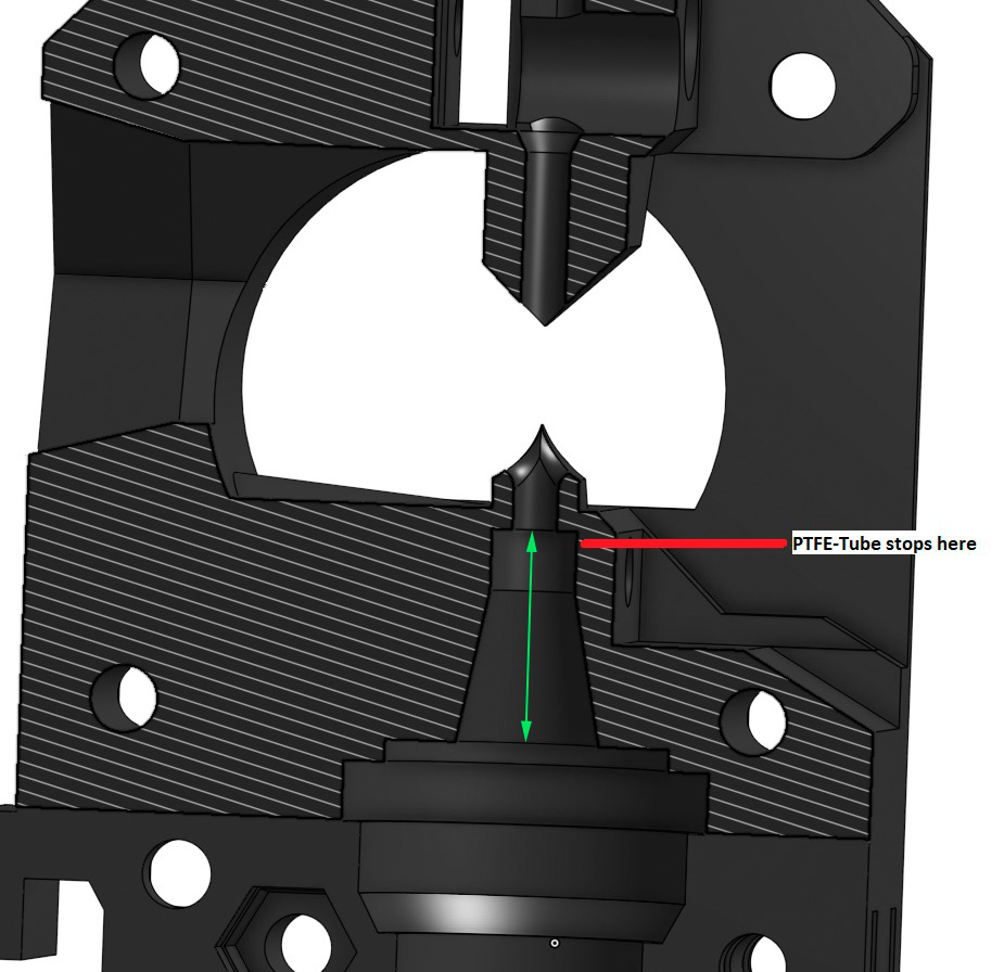
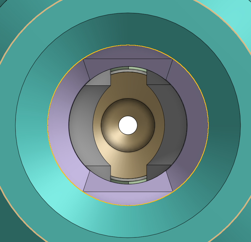
This is how I got the dimension 🙂

Re: Any ideas how to get this flexable material to print?
could someone explain the movement you mean? Is the 0.25mm here the same as the gap you are mentioning, or coincidentally also 0.25mm?
I placed the gears symmetric in the filament path. Should I move them?
Re: Any ideas how to get this flexable material to print?
0.25mm is the gap between the original extruder (R2 and R1) and the sweet spot where the gears should be. On my previous post, the 11.25mm dimension is 11.5mm in original extruder.
At first we heard that that gap should be 0.5mm and then I saw Petehagoras using 0.4mm. This gap is determined by the spacing of the gears and I could not find a document that explains what should be the appropriate spacing. I then sent an email to Bondtech to get some help and found the Bondtech extruder which is made with a spacing of 8.5mm between the two gears (or 0.25mm gap).
Hope that is more clear 😉
Re: Any ideas how to get this flexable material to print?
I am using 8.6mm spacing as shown in pic above. I had a reason, but need to review sketches. I think 8.5 is the minimum (max tooth penetration, addendum to dedendum). Since once side is idler, I wanted neutral position to allow for _some_ bidirectional arc to minimize axial offset. Soft filaments will allow more bite, but I want a general extruder.
Re: Any ideas how to get this flexable material to print?
During the first assembly of my reworked extruder I found that my PTFE was much longer than estimated. With help of someone from our community (Bear Upgrade for Prusa i3) we did several measurements on the PTFE tube length that goes out of the hotend, this length in green :
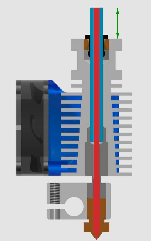
This length is not very consistent (onMK2s and MK3) and can vary between 17mm to 17.5mm
Do not know if this is very useful but better to share 😉