Z axis problems
Hi.
I've had a prusa i3 mk3 since November 2020, and it's been running great until recently. I changed the nozzle after a blockage, and now the z axis is always going out of alignment during calibration. If I am able to make it through calibration the first layer is too low on the left, perfect in the middle, and too high on the right. If I try to print anything like this, it separates from the print bed and the print fails. Any help would be appreciated.
Thanks


gantry
Have you tried to get the gantry level? I would remove the screws from the black threaded part that is on the threaded rod and try to level the gantry.
--------------------
Chuck H
3D Printer Review Blog
Re: Z axis problems
@Don: The calibration you mentionend can't have been the XYZ-calibration, right? Your x-asis gantry is even to the naked eye visibly way too sloped for the XYZ-calibration to succeed. You probably meant the meshbed-leveling, haven't you? How could that possibly have succeeded?
In order to level the gantry manually prior XYZ-calibration, the following is like what @cwbullet recommends but described in steps:
- Turn the printer off.
- Level the gantry in the lower position by hand by turning the spindles. Do no use that coarse tape measurement for that. Rather, position the nozzle slighly above the bed, move the x-axis carefully and slowly by hand from left to right and use a piece of paper under the nozzle to check the height difference.
- When the gantry is at least approximately leveled and low (thus: The black trapezoid spindle nuts have their in closest distance to the spindle bearings in the motor) loosen the screws holding the nuts, verify that they do not jam the spindle, then retighten them.
- Move the gantry fully up by hand until it bumps into both upper z-axis holders. Verify the level there too. The axis should be parallel to the frame.
- Finally, turn the printer on and make an XYZ-calibration according to the manual.
The main objective of the manual part of the preceeding procedure is to verify that the z-axis can make the full stroke on both sides and the nuts do not seize the spindles. The final gantry orientation is gained by the XYZ-calibration.
Whenever you accidentially turned one of the spindles by hand, I recommend doing a full XYZ-calibration. The meshbed-leveling grid heights are dependent on the orientation the gantry gets when bumping into the upper z-axis holders during XYZ-calibration.
In addition to that, doing it by the book that way makes the process reproducible. Doing it again should yield approximately the same grid height values. These can be displayed e.g. with a terminal program like pronterface with the command G81 or with an octoprint plugin. Even without that you can observe a measured slope when you print longer lines in x-direction. On a perfectly adjusted printer, the z-spindles to not rotate when printing a line in x-direction. If the bed is sloped, the splindles turn to compensate for that slope and keep the nozzle at constant distance to the bed. The same goes for the y-direction. In order to observe a rotating z-spindle easier, you can make a point with a white marker pen onto the black z-screw covers that rotate with the spindle.
Have a nice day.
Re: Gantry
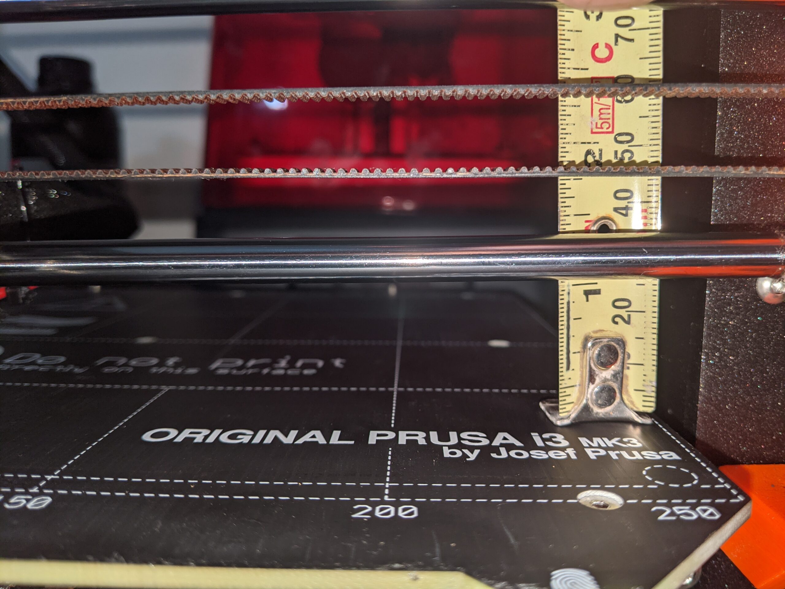
I've leveled the gantry several times. The pictures I posted show what happens to the x axis gantry as it goes through the xyz calibration. It usually happens while finding the calibration points.
RE: Z axis problems
@blauzahn I have slight issues with the my newly assembled MK3S+ kit and while searching for tips in here, I found also your recommendation below.
In my case, the gantry level seems to be fine (given the final prints) but only when I loosen the screws of one trapezoidal lead screw approx. 1-2mm. When i tighten the screws of BOTH lead screws equally, I can no longer rotate the z lead screws by hand, because it jams somehow. When loosening the left lead screw nuts slightly, the "jam" suddenly relaxes and everything works niuce and smoothely as expected. Thus I infer that I have a sligh skew somewhere. I did already check every detail of the assembly but cannot find the issue. But just keeping the one lead screw nut a little bit loose also seems not like a good solution to me, because the "play"/space would propbably introduce some unpleasent side effects.
In step 3 you say "loose the screws" in order to assure they do not jam/skew and "then retighten" them - this would fix my issue, but then the top nut holes for the screws are no longer in line with the holes of the x-carriage plastic build part the hex nuts are in.
Do you have any idea? 🙂
I would be glad for any feedback.
- Turn the printer off.
- Level the gantry in the lower position by hand by turning the spindles. Do no use that coarse tape measurement for that. Rather, position the nozzle slighly above the bed, move the x-axis carefully and slowly by hand from left to right and use a piece of paper under the nozzle to check the height difference.
- When the gantry is at least approximately leveled and low (thus: The black trapezoid spindle nuts have their in closest distance to the spindle bearings in the motor) loosen the screws holding the nuts, verify that they do not jam the spindle, then retighten them.
- Move the gantry fully up by hand until it bumps into both upper z-axis holders. Verify the level there too. The axis should be parallel to the frame.
- Finally, turn the printer on and make an XYZ-calibration according to the manual.
RE:
unscrew the top printed parts top of frame supporting 2 rods take the platic trapezoid nut of then screw theme onto x axis assembly then place it on so its level put back platic parts and do z calabration
Please help me out by downloading a model it's free and easy but really helps me out https://www.printables.com/@Hello_474427/models
RE: Z axis problems
Probably, the nuts push laterally against the holes within the x-end.
[...] but then the top nut holes for the screws are no longer in line with the holes of the x-carriage plastic build part the hex nuts are in.
It is also possible, that one or both nuts tilt with respect to the spindles when fastened.
Please recheck in the assembly manual step 4: z-axis assembly.
- Do you have the Original MK3S+ from Prusa or a clone?
- Did you deviate somewhere from the original design or the assembly manual?
- Do you have prior experience in assembly?
- Did you assemble the frame on the most planar surface available?
- Do you have some measurement tools?
- Did you experience any surprise during assembly? Except for the mentioned problem, of course.
- Are both x-end parts geometrically intact?
- Are the holes for the nuts within both x-ends clean?
- Are both x-ends fully pushed onto both x-rods?
- Are the z-spindles parallel to the rods, the frame and to each other?
- The z-bottom-parts must be well aligned, even though they can only be aligned within their screw holes. The faces of the z-bottom parts facing the z-motors must be planar. Do the z-motors sit flush with the parts? Once fully assembled, you will have to loosen the motor cables in order to lower a z-motor including its spinle, let alone take it out.
I recommend to tighten the nuts when the z-axis is close to its lowest height.