Re: Tired and indignant
Are you all sure you don't have some other issues, like slicer settings, etc? I have tuned my S3D settings and my walls are excellent. I am running the tagged 3.1.3 but with LA enabled (I compiled this version myself). It's been working like a champ on PLA, PET, and TPU. No way am I ready to go to 3.2 alpha, that is a mess right now IMHO.
Please don't assume the problem is entirely in firmware. With a good build and a tuned slicer, this thing is putting out excellent prints.
For our reference, can you try this with a single wall cube with zero infill and post some pics plus the gcode? Make sure to have light shining down the face of the cube to highlight the varied layers if they are there. This will let us see the difference in your version plus let us try it on our MK3s and compare. I will get my copy of S3D reinstalled and see if I get different results on my own as well.
Something I might try later on is doing something in vase mode so its one big extrude rather that doing a retraction and movements on layer changes etc.
Re: Tired and indignant
So, going down this slicer rabbit hole I started comparing some Gcode between S3D and Slic3r, and I think I am ready to dismiss the idea of the slicer being the problem. I will still actually print and test when I get home, but consider the following.
I took the Slic3r gcode that was known to have the issue (my 1 wall square, 40mm) and filtered out the first few layers (as I had a skirt). I then removed all lines from the gcode that were doing retractions and such, getting purely down to lines that were doing a movement down the side of the cube while extruding filament. Ended up with a bunch of this:
G1 X100.225 Y80.225 E0.00609 <-- wipe?

G1 X149.775 Y80.225 E1.67721

G1 X149.775 Y129.775 E1.67721

G1 X100.225 Y129.775 E1.67721

G1 X100.225 Y80.465 E1.66908

G1 X149.775 Y80.225 E1.67721

G1 X149.775 Y129.775 E1.67721

G1 X100.225 Y129.775 E1.67721

G1 X100.225 Y80.285 E1.67518

G1 X100.225 Y80.225 E0.00203

G1 X149.775 Y80.225 E1.67721

G1 X149.775 Y129.775 E1.67721

G1 X100.225 Y129.775 E1.67721

G1 X100.225 Y80.345 E1.67315

G1 X100.225 Y80.225 E0.00406

G1 X149.775 Y80.225 E1.67721

G1 X149.775 Y129.775 E1.67721

G1 X100.225 Y129.775 E1.67721

G1 X100.225 Y80.405 E1.67112

G1 X100.225 Y80.225 E0.00609

G1 X149.775 Y80.225 E1.67721

G1 X149.775 Y129.775 E1.67721

G1 X100.225 Y129.775 E1.67721

G1 X100.225 Y80.465 E1.66908
We know that this artifact can appear and disappear more than once in a single layer. I.e., the extruded wall may start too fat, get too narrow, get fat again, etc. Considering a one wall movement in the above gcode is literally one line of gcode with one extrusion amount defined, I don't see how the slicer could be causing the inconsistent extrusion out of the nozzle. But to break it down even further, I put the Linux to it:
brigandierr@ubuntu:~$ cat test.gcode | sort | uniq -c

    234 G1 X100.225 Y129.775 E1.67721

     58 G1 X100.225 Y80.225 E0.00203

     59 G1 X100.225 Y80.225 E0.00406

     59 G1 X100.225 Y80.225 E0.00609

     58 G1 X100.225 Y80.285 E1.67518

     58 G1 X100.225 Y80.345 E1.67315

     59 G1 X100.225 Y80.405 E1.67112

     59 G1 X100.225 Y80.465 E1.66908

    234 G1 X149.775 Y129.775 E1.67721

    234 G1 X149.775 Y80.225 E1.67721
The above command prints my filtered down gcode out, pipes it into sort, then pipes that into uniq -c which combines duplicate lines together and gives a count (which is represented at the start of the line) of how many lines were duplicates. Let's start with the three that had a count of 234:
    234 G1 X100.225 Y129.775 E1.67721

    234 G1 X149.775 Y129.775 E1.67721

    234 G1 X149.775 Y80.225 E1.67721
The above gcode corresponds to three sides of the cube. As you can see, those three sides all get an identical extrusion amount. Considering the artifact is around all sides of the cube and very erratic, I think it's safe to say that the gcode isn't the issue. It's using the same three commands for three sides of the cube. Now, the other lines of gcode for one of the sides:
     58 G1 X100.225 Y80.225 E0.00203

     59 G1 X100.225 Y80.225 E0.00406

     59 G1 X100.225 Y80.225 E0.00609

     58 G1 X100.225 Y80.285 E1.67518

     58 G1 X100.225 Y80.345 E1.67315

     59 G1 X100.225 Y80.405 E1.67112

     59 G1 X100.225 Y80.465 E1.66908
This is the variations of gcode used for the "front" side of my cube, along with the variations of the wipe it does there. I'm not sure why there are a few versions of this side, but you can see the difference is incredibly small. The extrusion amount is for the entire movement as well, so this wouldn't cause a line to get fat/narrow/fat/etc randomly throughout that movement. Also, if this randomness was the cause, we'd only see it on the front of the cube, as per above we have identical lines of gcode being used for the other three sides.
I will still test this out with a print just to see if there's any difference, but at this point I am willing to bet those people who have amazing walls haven't printed a very straight wall and looked at it under some light. Would be thrilled to see a pic of that without this artifact. 🙂
My MK3 Parts: [Bowden] [New Shoes] [TPU Micro Springs]
Re: Tired and indignant
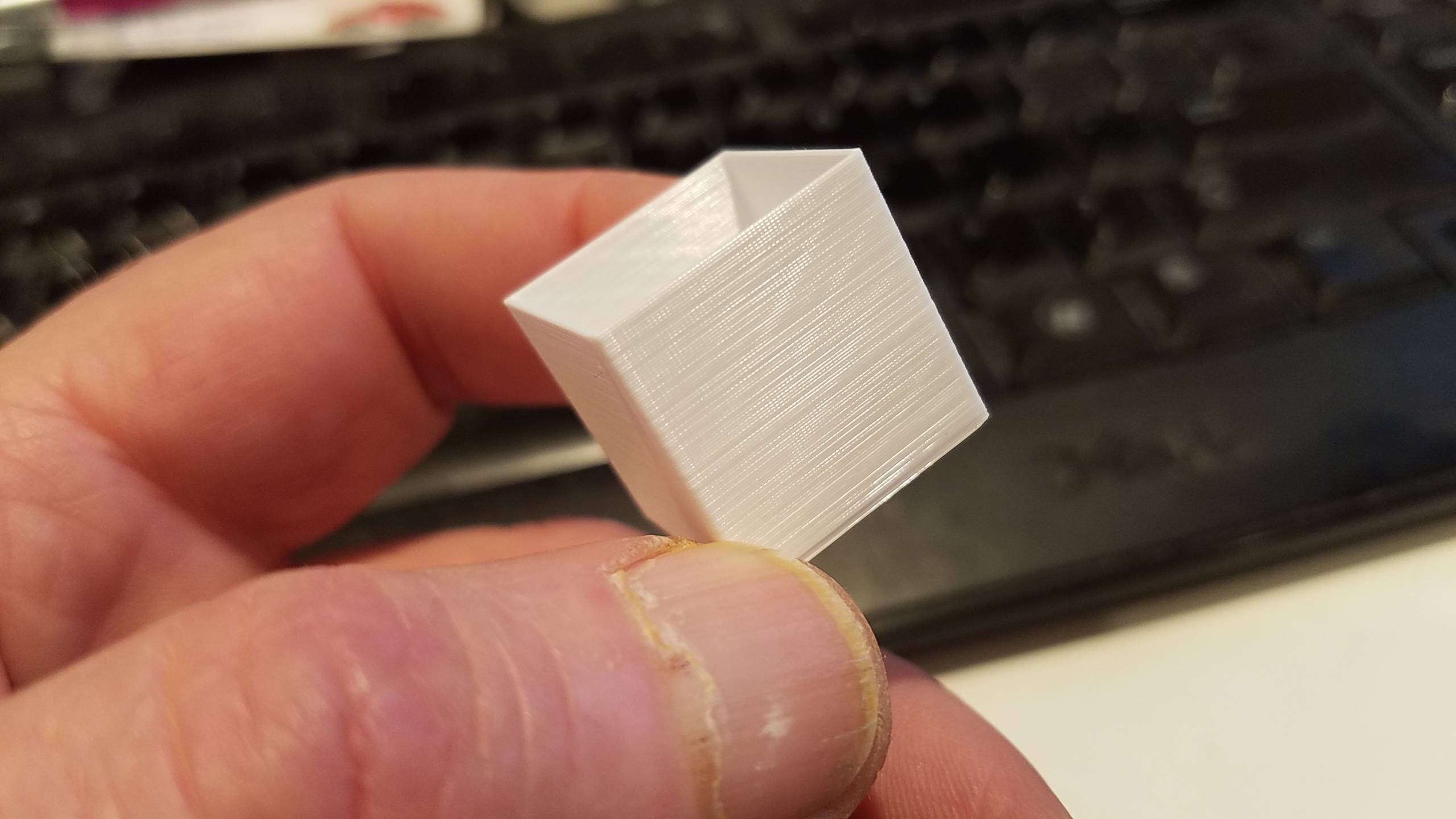
Here's a picture, but perhaps I didn't follow the spirit of the test... this was printed in Vase mode (Please ignore the bottom couple mm of this print, I had it running at 500% speed just to test something else. I then slowed it back down to 100%.)
Re: Tired and indignant
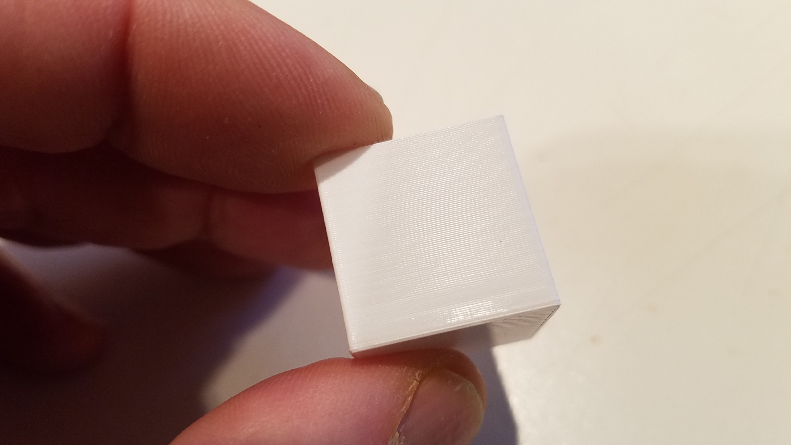
Here's about the worst view of the cube. This of course is using extremely bright lighting, white filament which shows things down to the nitty gritty detail, and believe me you cannot see this with the naked eye.
...and attached is the gcode for this.
Re: Tired and indignant
Here's a picture, but perhaps I didn't follow the spirit of the test... this was printed in Vase mode (Please ignore the bottom couple mm of this print, I had it running at 500% speed just to test something else. I then slowed it back down to 100%.)
I would say that looks identical to mine, and I can see the light extrusion moire going from top right towards bottom left. Is it possible to take a pic of it with light coming from above? This causes the fat layers to cast shadows onto the narrow ones. For example:
My MK3 Parts: [Bowden] [New Shoes] [TPU Micro Springs]
Re: Tired and indignant
Whoops, you beat me to it by adding another shot. Your second shot exhibits the same thing we are trying to fix. For many it may be good enough, but I want something more like this...
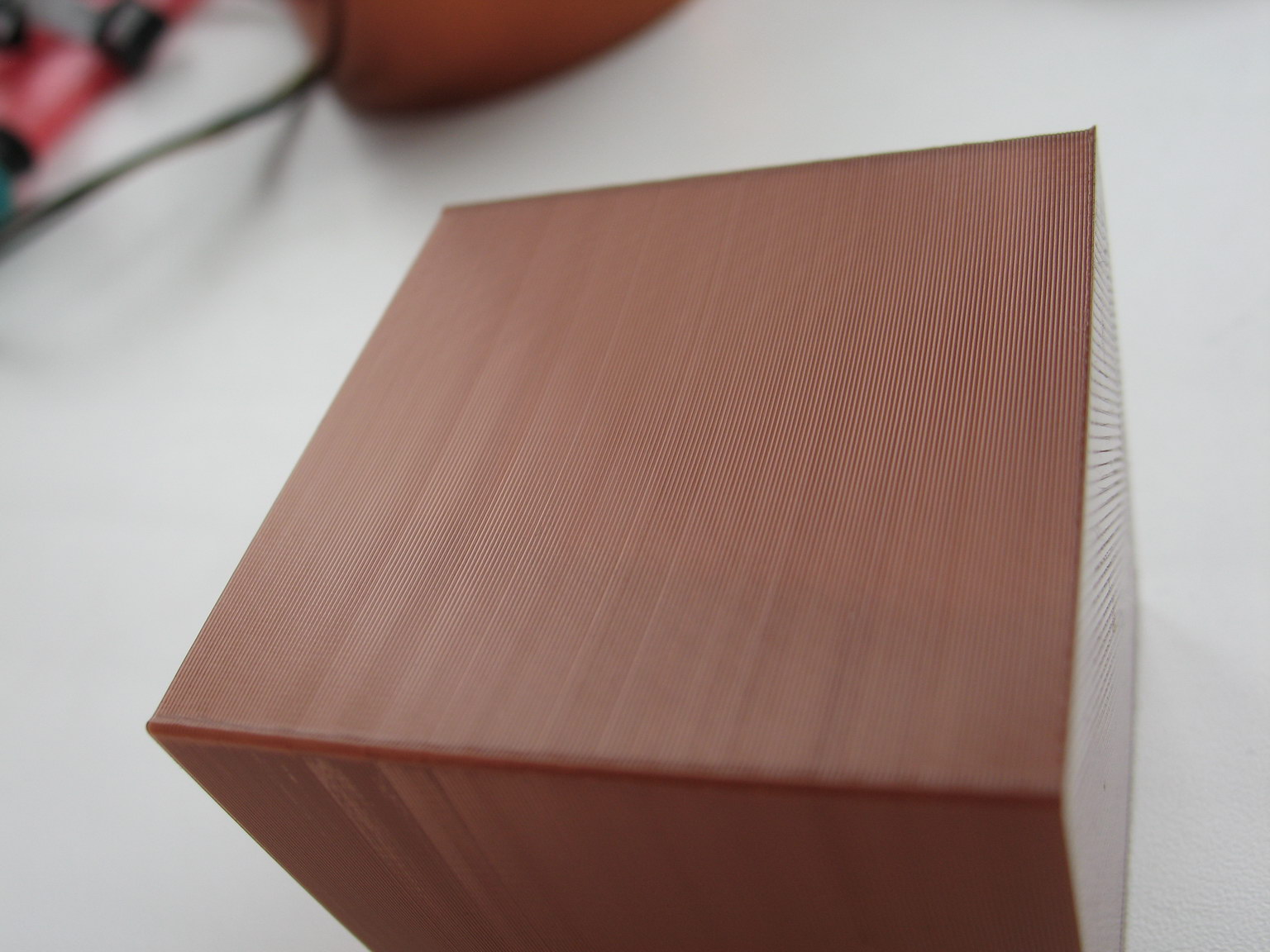
I am yet to get close to that with the MK3.
My MK3 Parts: [Bowden] [New Shoes] [TPU Micro Springs]
Re: Tired and indignant
Whoops, you beat me to it by adding another shot. Your second shot exhibits the same thing we are trying to fix. For many it may be good enough, but I want something more like this...
IMG_6790_resize.JPG
I am yet to get close to that with the MK3.
A Mk2 can do that, My Anet A8 can do that, but the state of the art MK3 cant get even close.
Im not sure what the next move is now.
Could the bondtech motor gear not perfectly not round? maybe as not everyone seems to have this problem. if there no pumping out loads could there now be flaw in them...
Im wondering if i could slip something else on the shaft and use a bearing as a tensioner
Re: Tired and indignant
0.3 layer height, I don’t know for it’s just my eyes but there looks more of a pattern to it
Re: Tired and indignant
0.35 layer height, some interesting results! The layers seem to stack better but there a aligning patten definitely there, it’s on all four sides and clearly visible! But the cause is still unknown
Re: Tired and indignant
I have the same issue.. Not as obvious here but it's pretty much the best I can get...
Re: Tired and indignant
Could this be caused by the tension system holding the bondtech gears together? As the teeth bite into the filament, tension goes up. As the tension goes up, the springs are going to give a bit. When the springs give a bit, the amount the bondtech gears mesh is going to change.
It seems to me this would cause the bondtech to not turn consistently. When I get home, I am going to print some rigid plastic spacers to replace the tension springs. It seems to me if you knew the perfect spacer size, you could make the bondtech 100% rigid while maintaining bite.
My MK3 Parts: [Bowden] [New Shoes] [TPU Micro Springs]
Re: Tired and indignant
Could be a good test or you could do them up solid with the spings there? I’ve had them in all sorts of tensions including very tight and it made no difference at all.
I have an different extruder gear I could try if I can figure out and easy way to swap it over.
It won’t drive like the bondtech does but something repeating consistently to me is something rotating, I won’t suspect x or y as it’s the same on all four sides
Tried it with the springs removed, the screws bottomed out and had enough thread left to do it from that position. I increased tension until there was good grab on the filament. Unfortunately, no change, the artifact is still there. Not going to bother with S3D either now that we've seen the S3D example has the same artifact.
Your .35 piece is interesting. I am going to try that on my end and see if I get similar results. If I do, I am going to play with the 3.2.0 Alpha extruder linearity correction (E-Correct in the menu) and see if I can effect a change in it.
My MK3 Parts: [Bowden] [New Shoes] [TPU Micro Springs]
Re: Tired and indignant
Ok. I've mainly been programming with interpreted languages and haven't programmed in c++ in ages. I finally got the alpha firmware compiled but it output two hex files. Theres one hex file with and one without a bootloader. Which one do I use? I don't want to brick this thing lol
Hi Chris,
I found this guide http://zaribo.org/blog/how-to-compile-and-modify-prusa-firmware-part-i-setting-up-the-environment/
the part that my help you is.
Uploading the firmware
After exporting the compiled binary two files are created in the directory “Prusa-Firmware\Prusa-Firmware-3.012\Firmware”
•Firmware.ino.rambo.hex
•Firmware.ino.with_bootloader.rambo.hex
The Rambo board has an installed bootloader already, so we only need the first file. It’s a good practice to rename it to a more speaking name. Since we have not changed anything in the source code a good name could be “Prusa-MK2-3.0.12.hex”
Follow the official Prusa guide to upload the compiled .hex file: http://manual.prusa3d.com/Guide/Upgrading+firmware/66
Congratulations, when you successfully arrived here. You have set-up a working environment for compiling the firmware. In the second part of this tutorial, we will discuss how to change the firmware for Zaribo and also we will discuss some useful tweaks.
When I done a compile mine I had only one file so I cant be 100% sure, I guess with you experience you'll understand it better than I did.
Thanks for coming on board, have you managed to discover anything?
Re: Tired and indignant
Regarding the vertical banding as in edward's picture: One could calculate the (x or y) motor angle equivalent to the ripple distance. If it is some multiple of 1.8°, this wold be a strong indication that it is stepper motor related and not say linear ball bearing ripple (which I also find noticeable).
Everyone aware of microstep issues and possibilities with the trinamic drivers?
http://www.geckodrive.com/support/step-motor-basics/accuracy-and-resolution.html
https://www.trinamic.com/fileadmin/assets/Support/Appnotes/AN026-Adaptive_Microsteptable.pdf
https://github.com/prusa3d/Prusa-Firmware/blob/MK3/Firmware/tmc2130.cpp line 895 (not sure if this is the right place though...)
- Martin
- Martin
Re: Tired and indignant
Regarding the vertical banding as in edward's picture: One could calculate the (x or y) motor angle equivalent to the ripple distance. If it is some multiple of 1.8°, this wold be a strong indication that it is stepper motor related and not say linear ball bearing ripple (which I also find noticeable).
Everyone aware of microstep issues and possibilities with the trinamic drivers?
http://www.geckodrive.com/support/step-motor-basics/accuracy-and-resolution.html
https://www.trinamic.com/fileadmin/assets/Support/Appnotes/AN026-Adaptive_Microsteptable.pdf
https://github.com/prusa3d/Prusa-Firmware/blob/MK3/Firmware/tmc2130.cpp line 895 (not sure if this is the right place though...)
- Martin
Very interesting reading, I think it looks the complexity of the stepper drivers and the setup of the associated 'Bit and bobs' can get pretty complicated and it seems there plenty of room for error there, we can see what commits go in over the next week weeks unless someone can figure it out in the meet time.
Re: Tired and indignant
Could the bondtech motor gear not perfectly not round? maybe as not everyone seems to have this problem. if there no pumping out loads could there now be flaw in them...
Im wondering if i could slip something else on the shaft and use a bearing as a tensioner
Actually the bondtech drive is overconstrained as I see it. There is the gear connecting motor to idler and there is the teeth biting into the filament from both parts, forming a second pair of gears. Ideally both have an 1:1 ratio, but if the diameters are slightly different, this will cause a lot of friction. Anyway I am not sure why they used this dual drive extruder. I never had an issue with my MK2S regarding the extruder.
So I guess easiest way to take this out as possible error source is as jonathan mentions, remove the second gear and just put a ball bearing into place (or any matching roller, as the bearings are separate anyway).
- Martin
- Martin
Re: Tired and indignant
Could the bondtech motor gear not perfectly not round? maybe as not everyone seems to have this problem. if there no pumping out loads could there now be flaw in them...
Im wondering if i could slip something else on the shaft and use a bearing as a tensioner
Actually the bondtech drive is overconstrained as I see it. There is the gear connecting motor to idler and there is the teeth biting into the filament from both parts, forming a second pair of gears. Ideally both have an 1:1 ratio, but if the diameters are slightly different, this will cause a lot of friction. Anyway I am not sure why they used this dual drive extruder. I never had an issue with my MK2S regarding the extruder.
So I guess easiest way to take this out as possible error source is as jonathan mentions, remove the second gear and just put a ball bearing into place (or any matching roller, as the bearings are separate anyway).
- Martin
I do have spare mk2 style, I couldn't come up with any easy way to change it unless I remove loads of bits, I might attempt it this afternoon.
i'm hoping the idler gear will still work but just not being driven by the motor and just rolls over the filament.
Re: Tired and indignant
I guess the easiest way to test would be not to replace the motor side but remove the idler side instead.
It wouldn't test if the motor gear is O.K. but it would test the grabbing from both sides theory