Testing Features
Was a bit bored this afternoon waiting for computers to do more bad things and played with Prusa Slicer 2.3.0a2 and 3DBenchy.
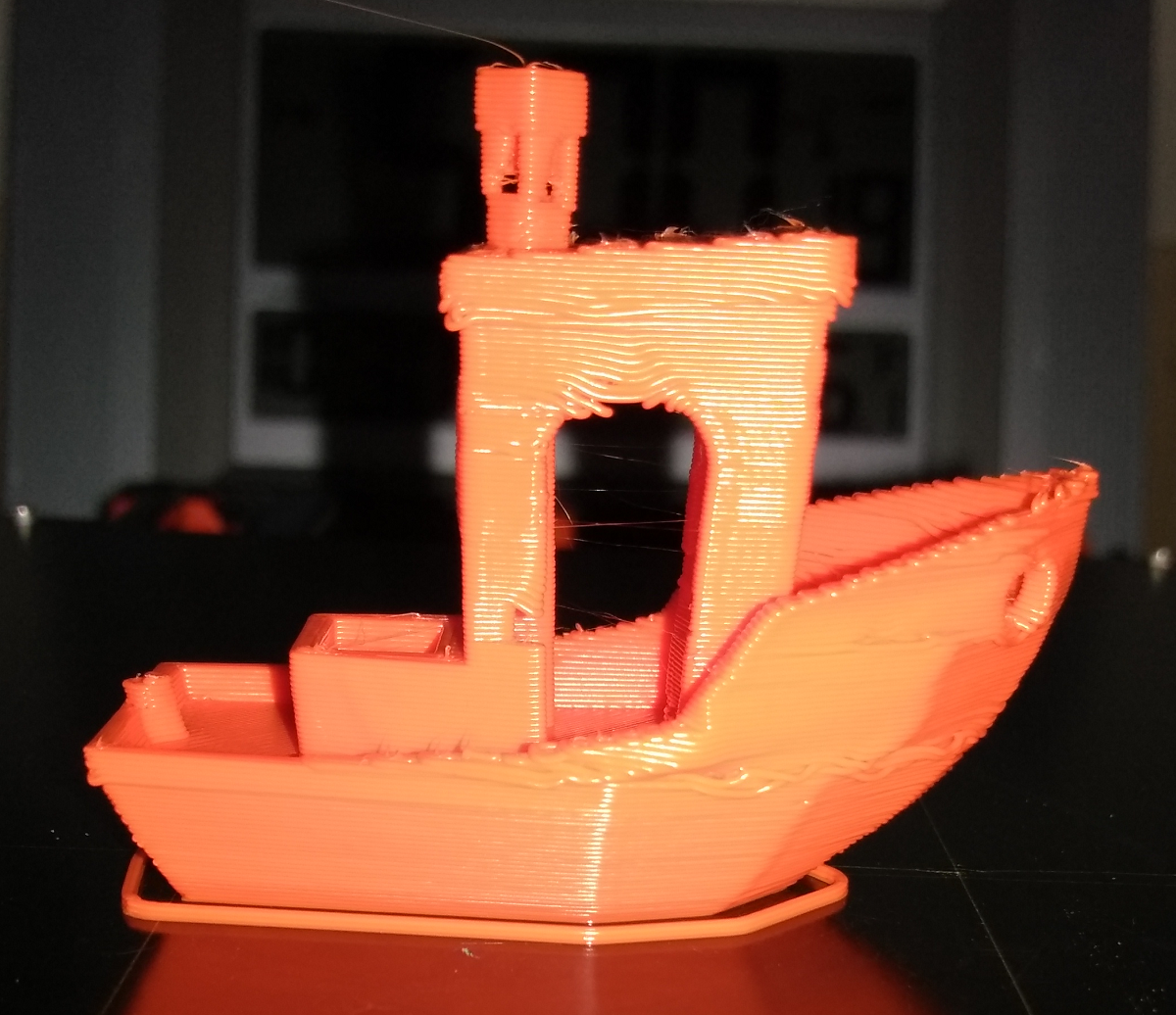
After printing, thought it would be an interesting test of helper knowledge. I changed a value that I didn't think would have much effect at all. Not sure I could figure it out from photos alone - and I printed it - but can anyone tell me what happened? And yes, this is the Prusa 3dBency sample STL. Four settings were changed. Elephant foot was set to zero. Layer height set to 0.35. Perimeters width set to 0.6mm.
The other change is the one that really surprised me: doing something I really did not expect.

RE: Testing Features
I’d take a guess you set a value on the slice resolution ? Maybe around 1mm
RE: Testing Features
1.25 to be precise.
I was not expecting facets. Plus, why can the stern post be as small as it is yet the stack is clipped twice as much? Then there's the question of why isn't Z being clipped? The doorway arch almost looks normal if you forgive the sloppy over-extrusion I was looking for.
Then there's the slope of the hull: if X and Y are being clipped back to 1.25 mm - how can one layer only move an extrusion width? Much less than the resolution I set. So, I think this shows a real defect.
RE: Testing Features
Well the z being ok makes sense to me as when it slices it does so layer by layer without any look ahead so each and every layer is going to be independent.
As to what the setting is actually doing, I don’t really have a good idea, except I think it’s similar to using reduction on a svg. While I can follow code if forced it’s not something I like to do and haven’t really been through the slicer code. I suspect that it removed intervening points below the value you set, so that on a perimeter it will end up reducing the amount of points. I think when the island is smaller than the value that it can’t/won’t remove points so the small post at the back is mostly ok. You could view that as a defect but it’s a borderline one and possibly better than removing features completely.
On the hull only moving a bit it also makes sense as if it’s only removing points then many points will still align between layers (mostly).
Think of a pure cylinder that has 64 points around the circumference, if you reduce that to 8 points then it’s going to make a octagon and assuming it starts at the same spot on each layer the edges would all align. If it started offset then you would probably get a spiral as it rises.
RE: Testing Features
My take on it is to think of it as snap-to-grid, and resolution sets the grid spacing. But the print doesn't appear on first take to follow any such rule -- at least entirely throughout the slice. The application seems almost random, and changes by layer, as if it is also watching for some other priority. The two cylinders are an example of this: Both are stacks of circles. If the grid is 2 mm, a 2 mm circle will be a square, but an 8 mm circle will be a larger polygon. But that isn't what is happening on the boat: both small and large are square.
I need to go back to the Slic3r manual and read up on what this is supposed to do... and if I am ever curious enough go to the source... though every time I start looking there I find more surprises I didn't want to know about (that open source community built lack of structure and consistency thing).
RE: Testing Features
I don’t think there’s anything like a grid. Pick a starting vertice, follow along the path until you get to a vertice a greater distance away than your setting, 1.5mm in your example, remove and vertices between them. Repeat until you get back to the starting point. That will make it more angular like in your example with benchy. I think if the path is less than 1.5 then it doesn’t do anything with the path so no verts get removed. Repeat for all islands on the layer and then repeat on next layer.
RE: Testing Features
OpenSCAD has a similar resolution feature that can be changed on the fly. Reducing it produces similar angled circles, to the point that you can use it to produce different shapes. Here's a shape generated with the resolution set to 90:

Here's the same with resolution set to 3:

Since current slicers are generating gcode that consists only of straight lines, your result makes sense. PrusaSlicer just handles resolution differently. I can reproduce the same effect in PrusaSlicer. Here's a circle with resolution set to 6. Unlike OpenSCAD, lower resolutions (higher values) don't map directly to number of polygon sides and I don't seem to be able to get it any coarser than a hexagon.

Marlin firmware contains routines for handling arcs, but my understanding is that it's not widely implemented yet. I'm not aware of a slicer supporting generation of arcs in gcode.
RE: Testing Features
Something odd it going on ... this result doesn't make sense, and the fact layer 1 is hosed makes me consider it really is unexpected behavior. I'll be doing some more work on this and likely posting a bug on github.
This cone is 50 mm tall, 50 mm diameter, resolution is set to 10 mm ... the various points where the slice changes in large steps is at z=16.20 mm; and the step change from octagon to square is definitely not anything to do with any 10 mm distance I can easily see. None of the base sides are 10 mm or multiple, none of the intra-vertices distances is 10 mm, none of the corner to corner distances come close to 10 mm. So just what exactly does this 'feature' do?? It is not doing what I thought it did at all -- lol. Oh, and changing to 1 mm resolution simply moves the step change higher up the cone, and changes side counts to 16 below the step, 8 above the step, adds a new step to 4 higher, and instead of clipping the cone at 10 mm per side (if that is what the top square measure), the height is now closer to the raw part and looking like 1 mm.

RE: Testing Features
Well, this conversation on GitHub hints the feature is to reduce slice time for larger models. Implies setting is intended to be low, sub millimeter. It also hints Prusa knows it is broken for intralayer.
https://github.com/prusa3d/PrusaSlicer/issues/2040
|
Thanks for the hint on reducing the resolution of slices. We have had some bad experience with this feature, introducing visible artifacts by simplifying successive layers independently from each other, thus reducing a point on one layer while keeping a point of the same triangle edge on the other layer. We may re-evaluate the feature for small reduction rates though.
|
Timocop commented on Apr 3, 2019 •
I found a solution for your slow slicing with "Avoid crossing perimeter" enabled. The problem are high polygone models. The resolution is set 0 by default (unlimited) which makes slicing complex models alot harder and slower. Since it loops though all perimeters and finds the perfect center. You should set the resolution to 0.01 (Cura default) this shouldnt sacrifice any detail but redues slicing time by ~50% (and more) in my compare tests.
Benchy 250% scale slice test case:
Res 0 : Slicing finished in 4:05min
Res 0.01 : Slicing finished in 0:33min
No avoid / Res 0 : Slicing finished in 0:14min
No avoid / Res 0.01 : Slicing finished in 0:10min