Simple CAD design giving me slicing issues
Hi guys,
As I have said, I'm new to this world of 3d printing and trying to understand why Slic3r is slicing the way that it does.
The simple design is basically a credit card sized pattern with a depth of 1.5mm.
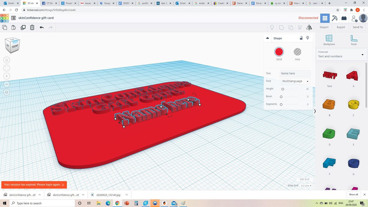
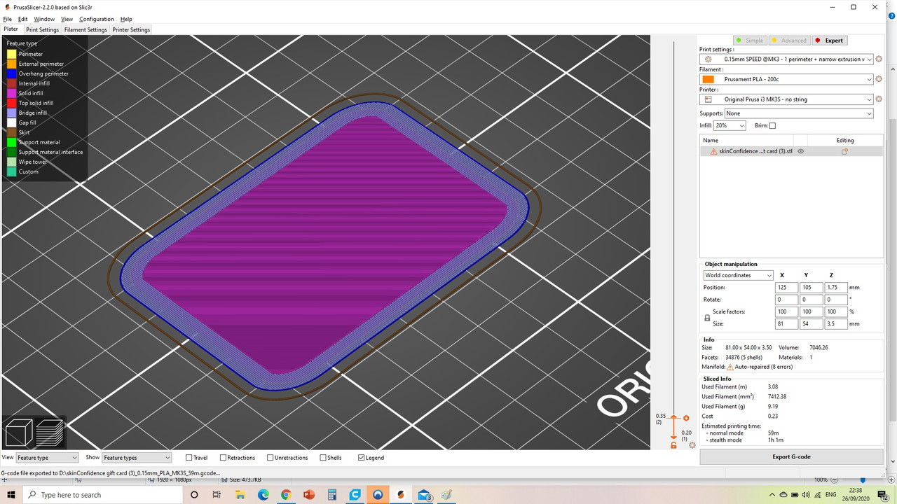
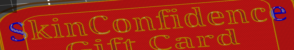
When I slice it, the bottom layer is absolutely fine but the second layer is not printing very well. This layer is longer and wider than the first and the portion that 'overhangs' the first layer is filled by bridging infil. The thing is, the perimeter of the second layer doesn't adhere very well and I'm not surprised as the extruder has moved vertically.
Here are the layers:
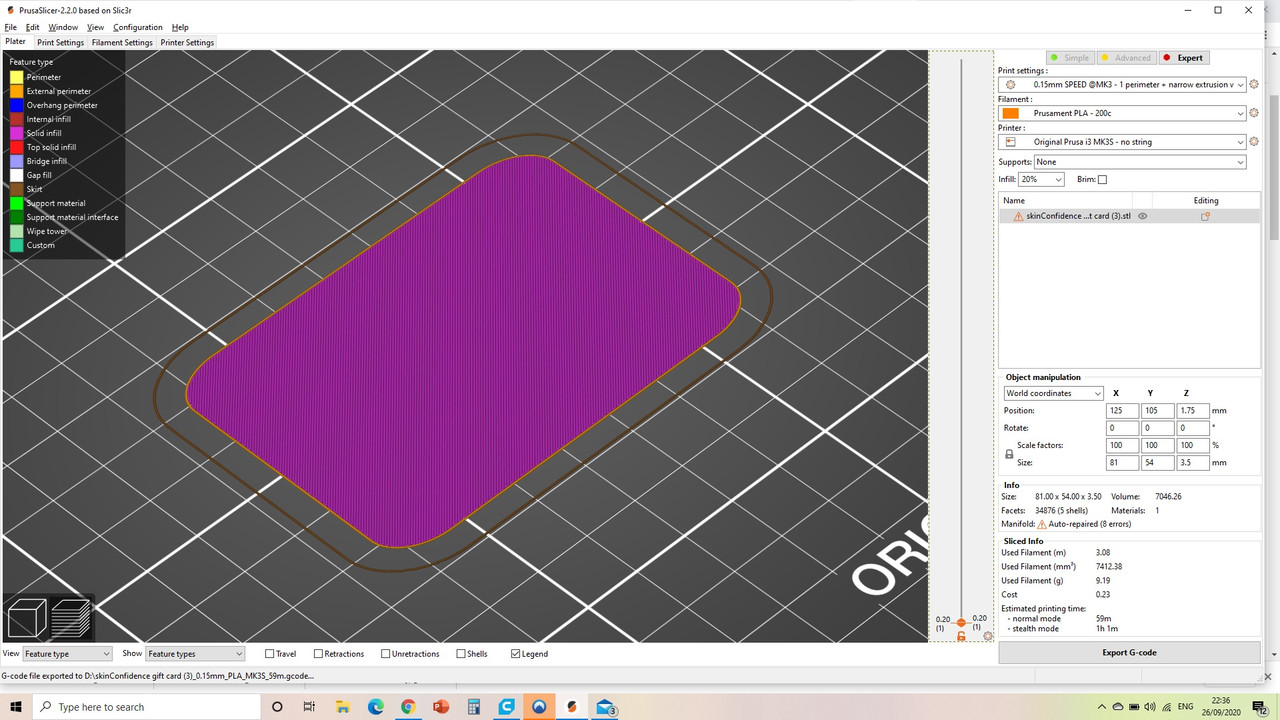
I don't really understand why all the layers of this pattern aren't the same size with a common perimeter rather than this overhang and bridging business. Also is there a ways I can alter the settings in order for the CAD to be sliced in this more logical way?
Many thanks.
RE: Simple CAD design giving me slicing issues
Please save your Prusa slicer project as a .3mf file , zip it into an archive and attach that here. That way we can debug it much easier as the project will contain the file and all your slice settings.
Must be zipped up or the forum won’t let you attach it.
RE: Simple CAD design giving me slicing issues
Yes, please share your .3mf or .stl files and you will get a few volunteers to test.
Raised lettering on a solid base should definitely slice and print with no issues.
RE: Simple CAD design giving me slicing issues
This is what I thought. I have been working all day, let me get this for you now.
RE: Simple CAD design giving me slicing issues
Please see below, I have attached the file.
Bear in mind that I have played around with the settings so the lettering prints out well. I have also turned down the temp to reduce stringing.
Look forward to hearing back.
Thank you.
RE: Simple CAD design giving me slicing issues
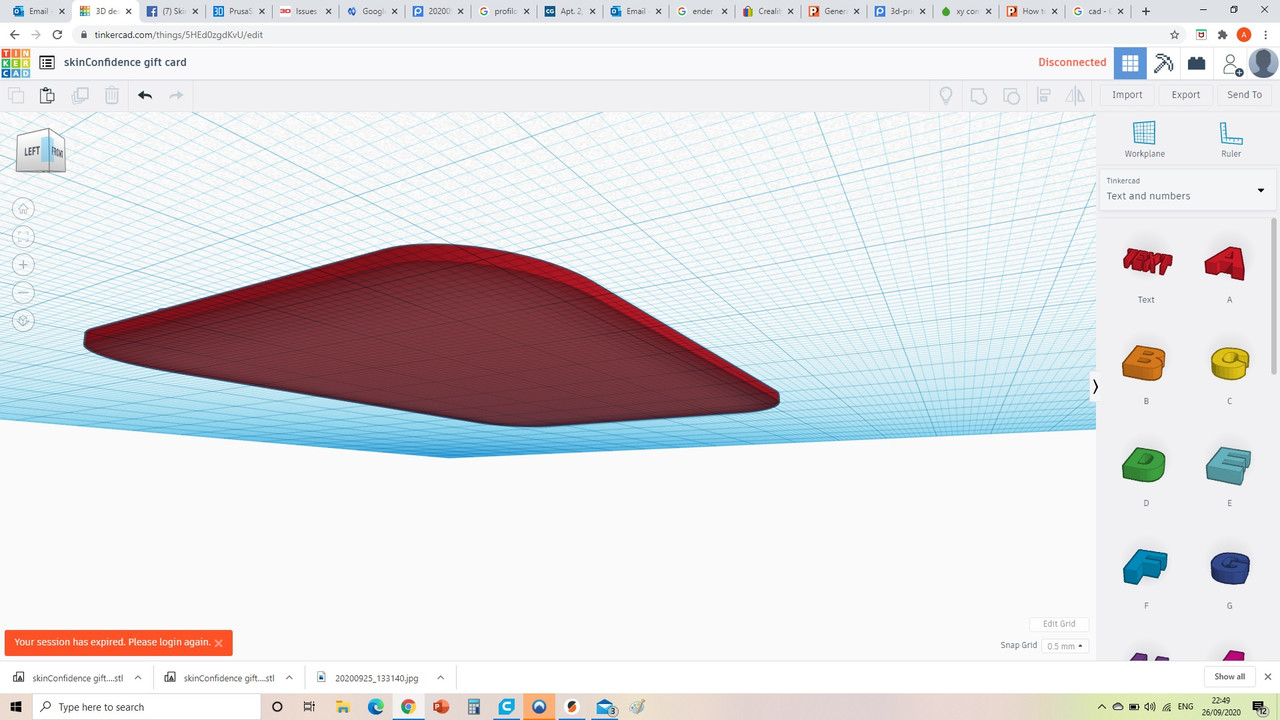
As I thought. Your baseplate that you have the letters on isnt flat. It curves slightly on both the bottom and the top. That is why the outer edge is printed as bridging, because the design dictates that. Its also apparent on the top, as the S and E (outside letters) dont actually connect to the surface below them, except in the middle where the base is an extra layer thick, they are printed mid air too on the end ones. Look at layer 11 on the preview.
RE: Simple CAD design giving me slicing issues
I think when you added a bevel to the thin rectangle it applied it equally proportionally to all the edges. Which gives you this - this is the bottom of your card. Its the same on the top except with all the letters. That is what the triangles of the stl are made up of.

RE: Simple CAD design giving me slicing issues
Oh dear,
I feel quite silly. Thank you for pointing this out and making my evening!
Best wishes!
RE: Simple CAD design giving me slicing issues
No problem. The whole 3d cad is a lot of learning. You might want to install some form of simple stl viewer to check out stl files (both your own and downloaded ones).
I usually model in Blender which has some very good 3d print checking tools that you can activate but for simple checking of stl files I like to use 3d-tool basic https://www.3d-tool.com/en-cad-viewer-download.htm Has a nice cross sectional viewer too considering its free for the basic version.
RE: Simple CAD design giving me slicing issues
Sure,
I will check it out now!
RE: Simple CAD design giving me slicing issues
Just as an alternative you can also use CraftWare (from craftbot) to show STL files. It is meant as a slicer, but works fine as a STL viewer with bisect capabilities. CraftWare is free and works great on Windows, Linux and Mac.
Have a look at my models on Printables.com 😉
RE: Simple CAD design giving me slicing issues
When I saw you were using TinkerCAD, my first thought was that filleting/beveling might have caused your problem. I mostly use Fusion 360 these days but I go to TinkerCAD quite frequently. It's so easy to use and it's straightforward to create simple models or to make modifications to existing STLs, compared to other tools such as Meshmixer.
A few thoughts on TinkerCAD that may be related to this topic:
- While TinkerCAD is actually surprisingly powerful once you discovered some of its more obscure features, it doesn't have great ways to apply fillets. I assume you used a box shape and then the radius option. Unfortunately, it applies the radius to all edges equally, so you will end up with rounded edges at the bottom as well -- this is what you saw in your design. The only way you can apply fillets to selected edges only (such as the vertical ones) is to use the MetaFillet shape generator, which you can find in the right-hand pane under Shape Generators/All. Alas, the shape generators are displayed in what appears to be random order, so you may have to browse through a dozen pages until you finally find it (but you can then add it to your Favorite shapes). MetaFillet works great but it's a royal pain to size it and align it properly with the edges you like to fillet.
- When you add any object including lettering to a flat surface, make sure you use the D tool to properly drop it onto that surface. To this end, create a temporary workplane using the Workplane button or W on the surface you want to put the lettering on, then select the letters and use D to drop them onto the workspace.
- Make sure you select all elements and group them before exporting as STL.
- In my experience, TinkerCAD generates STLs with issues quite frequently (as you can see from the warning PrusaSlicer showed you in the screenshot you shared). So whenever I import a model from TinkerCAD and see an error message I run it through netfabb (right-click on the model to get to that option) and then Export to STL (also right-click on model) to generate a "fixed" version.
TinkerCAD is a great tool but not without its issues.
RE: Simple CAD design giving me slicing issues
@fuchsr
They were some comprehensive tips right there!
The D tool is exactly what I need because currently I am having to manually raise the height of the text exactly to the surface of the platform. I am familiar with the workplane but not the D tool - I have had a look on TinkerCAD but cannot seem to find the 'D tool'. Where is it?
RE: Simple CAD design giving me slicing issues
@neophyl
Thanks! I have got this now. Looks quite detailed so I will have a play with this
RE: Simple CAD design giving me slicing issues
Is it possible to use a wider extrusion width for the body of the model but for the layers consisting of lettering, to use a narrow extrusion width - this would of course save time.
So what I am asking is if I can select for each specific layer a different extrusion width and whether other settings can be altered on layer to layer basis - This would be very helpful indeed.
Regards,
Atish.
RE: Simple CAD design giving me slicing issues
You can use either normal modifiers or height range modifiers. There are a bunch of different settings you can apply to those modifiers, including extrusion widths. Bear in mind that you cant practically go for a width less than your nozzle width without causing potential print problems. Once you have the modifier type setup you can use the Add Settings option which will access the full range of options. The 'Infill' & 'Layers and Perimeters' contain the basic ones but the Add Settings has all of them including more infill and layer ones than the basics.
You can also vary the layer height used for different sections though with the variable layer height tool without using modifiers. This is used to speed up printing so thicker layers are used where the part is straight up/down but finer layers on things like curved surfaces. That will probably get you greater gains than adjusting extrusion widths.
RE: Simple CAD design giving me slicing issues
@neophyl
Good tip about extrusion width being small than nozzle diameter. I was actually running 0.05mm shy of the standard 0.4mm tip. But having said that, I just got my amazon delivery for a range of tip sizes. From 0.2mm all the way to 1.0mm. I understand that PS has presets for 0.25 and 0.6. So I have ordered some separate 0.25mm tips that were not included in the set.
Ok, I have found the layer height modifier function. I will have a tinker with this. After all, we are all a bunch of tinkerers!!!! Ha.
RE: Simple CAD design giving me slicing issues
@atish8888
It's one of the "hidden" tools in TinkerCAD. There's no menu option for it, you just select a shape, then press the D key on your keyboard, and voila it'll drop down to your current workplane.
Bonus tip:
Check out https://blog.tinkercad.com/keyboard-shortcuts-for-the-3d-editor. It's a convenient crib sheet of keyboard shortcuts.
Extra bonus tip:
Another hidden but handy feature is that you can double-click on a group to quickly edit a component of the group without having to go through Ungroup and Group again.
RE: Simple CAD design giving me slicing issues
@fuchsr
You my friend have made my tinkering lifestyle much easier! Thank you.