Re: life adjust Z - my way
Just 1 question adding . when i print lot of piece (like the one for the Ikea lacq table) btween each piece i have some spider threads , very think and easy to take it out . but just wonder me if you guys have same ? is normal or , should not have....?
This is called oozing or stringing. It's normal to certain degree. You can adjust this with retraction and temperature settings.
Check this site. You will wind most of the cases with images and the root cause: https://www.simplify3d.com/support/print-quality-troubleshooting/
ok i got it , i heard about this software but need to buy and for now seems complicate need to study
i presume that not everybody who are using 3d printer and the prusa one are using this soft to solve all issue !!
Re: life adjust Z - my way
ok i got it , i heard about this software but need to buy and for now seems complicate need to study
No, you don't have to buy it. This troubleshooting page is not slicer specific. You can find all the settings in Slic3r PE.
Often linked posts:
Going small with MMU2
Real Multi Material
My prints on Instagram
Re: life adjust Z - my way
ok i got it , i heard about this software but need to buy and for now seems complicate need to study
No, you don't have to buy it. This troubleshooting page is not slicer specific. You can find all the settings in Slic3r PE.
thanks but on website i don't find free !! only 2weeks and refund !! and i use the SLic3r but without any new set up or change any parameters am not familiary with ..i think it's take time before play with the parameter or find the right one or touch the G-code too...but seems a good soft post pro
big problem during night print , the brim is warping on corner after a while don't understand why as during the 5 line is good and after is warping !!
Re: life adjust Z - my way
Okay, so I managed to snap a picture. The top left keeps printing with gaps. My Live Z is currently at about -0.625. That seems to give me the smoothest print on the rest of the square, but no matter what Z setting, I still have those gaps. I've also tried messing with the bed level adjustment and doing -50 on all 4 points had zero effect on that area. I'm at a loss 🙁
Anyone have any thoughts on this? No matter what I adjust, I still get gaps from about the middle point to upper left. 🙁
Re: life adjust Z - my way
THIS IS MADDENING!
I have occasion to change filament colors, so I decided to recalibrate the Live Z Adjust. (It was never quite right before, anyway...)
Things were a tad... "wavy" at -1.250, so I adjusted downward, beginning at -1.225, which resulted in many gaps and little--if any--adhesion between the lines.
To make a long story short, I wound up back nearly where I started--at -1.245.
My instructions stated:
If the surface looks like loose srtings of spaghetti, Live Z is too High need to go bigger negative number
If the surface looks rippled and wavy, then Live Z is too low, need to go smaller negative Live Z number
If the surface is nice and smooth, you are about right.
Now... what if I get spaces between the lines AND ripples/waves at the same setting? (Cuz that's what I've got) 😕 😡

I can't remember the movie, but the line was... "I'm going... MAAAAAD!!!!"
That's "MISTER Old Fart" to you!
Re: life adjust Z - my way
[...] Things were a tad... "wavy" at -1.250, so I adjusted downward, beginning at -1.225, which resulted in many gaps and little--if any--adhesion between the lines.
Hang on... if you went from -1.250 to -1.225, you were moving UP. Now with the day I'm having, I could be wrong so double-check me, but more negative is lower. Less negative is higher (zero is above the bed).
[...] Now... what if I get spaces between the lines AND ripples/waves at the same setting? (Cuz that's what I've got)
Is that pic the 75x75 surface gcode from this thread or did you slice it yourself? Were you making adjustments as it was printing?
Overall, it looks low to me. The gaps would normally indicate you're high, but even those layers look a bit mushed to me. From what I can make out on the picture, it looks like it's all solidly anchored. Does any of it lift if you rub it?
Write down your settings so you can fall back if needed, but I'd start going up (less negative) by 0.02mm increments from where you are (-1.225, -1.205) until you get actual stringy results. If the filament comes up with a light rub, it's too high. Then come back down (more negative) slowly from there.
Re: life adjust Z - my way
Hang on... if you went from -1.250 to -1.225, you were moving UP. Now with the day I'm having, I could be wrong so double-check me, but more negative is lower. Less negative is higher (zero is above the bed).
I followed the directions I copied/quoted above. They must have been correct, because the waves were worse where I started at -1.250.
Is that pic the 75x75 surface gcode from this thread or did you slice it yourself? Were you making adjustments as it was printing?
Yes. It's the updated version at the bottom of the OP of this thread. On the first square, I went from -1.250 down to -1.225. That was too stringy, so on the second square, I started at -1.237 and went down to -1.245, which was good for the small area printed at that setting. The last square (attached above) was entirely at -1.245, which like all the others, produced mixed results.
Overall, it looks low to me. The gaps would normally indicate you're high, but even those layers look a bit mushed to me. From what I can make out on the picture, it looks like it's all solidly anchored. Does any of it lift if you rub it?
Yup. The thin area circled (left side) has little/no adhesion to each other, and light goes right through the spaces.
Write down your settings so you can fall back if needed, but I'd start going up (less negative) by 0.02mm increments from where you are (-1.225, -1.205) until you get actual stringy results. If the filament comes up with a light rub, it's too high. Then come back down (more negative) slowly from there.
If you look at my numbers, I've been adjusting by even smaller increments than that. At -1.250 it's wavy with no stringiness. At -1.245 and -1.237, it's a mix of stringiness & waves. That's what's making me cray.
FWIW, waves are always on the right; stringiness always on the left.
That's "MISTER Old Fart" to you!
Re: life adjust Z - my way
If the surface looks like loose srtings of spaghetti, Live Z is too High need to go bigger negative number
If the surface looks rippled and wavy, then Live Z is too low, need to go smaller negative Live Z number
If the surface is nice and smooth, you are about right.
Now... what if I get spaces between the lines AND ripples/waves at the same setting? (Cuz that's what I've got) 😕 😡
assuming the whole print was done at the same settings,
I would check out the printer built to ensure everything is as specified...
run the Z axis to the top until both Z motors stall,
make sure the Y axis smooth rods are both properly seated in their cups and that the cups are seated on the frame rails,
make sure that the Y axis linear bearings are properly seated.
make sure the bed is properly attached to the Y axis platten...
good luck,
Joan
I try to make safe suggestions,You should understand the context and ensure you are happy that they are safe before attempting to apply my suggestions, what you do, is YOUR responsibility. Location Halifax UK
Re: life adjust Z - my way
assuming the whole print was done at the same settings, √ (exactly as instructed)
I would check out the printer built to ensure everything is as specified...
run the Z axis to the top until both Z motors stall, √ (many, many times)
make sure the Y axis smooth rods are both properly seated in their cups and that the cups are seated on the frame rails, √ (re-checked several times previously, and again)
make sure that the Y axis linear bearings are properly seated. √ (re-checked several times previously, and again)
make sure the bed is properly attached to the Y axis platten... √ (re-checked several times previously, and again)
good luck,
😐
I DO appreciate all the help, but I can't help the feeling that there's something else not right. Faulty heat bed? Faulty PINDA? I'm now seeing that other folks are having to make Z-Adjustments higher (lower?) than -1.00. That's something (concerning me less). We're trying to locate/beg/borrow/steal an infra-red camera to verify/rule out the heat bed. I don't own any electronic testing equip. to verify/rule out the PINDA. Regrettably, I may have to pick a compromise setting and just go with that (though I really can't get a consistent bottom finish... 😥 ).
I hope you can understand my frustration.
Has anyone any thoughts on why the strings/waves are consistently in the same places (strings-left; waves-right)? Clue?
That's "MISTER Old Fart" to you!
Re: life adjust Z - my way
Hi Rufus,
the Extruder runs along the X axis smooth rods, which are notionally straight and notionally at right angles to the Y axis smooth rails
the heatbed is intended to be parallel to the Y axis smooth rods.
if these conditions are correct, then there should not be a problem
If, for some reason the X rails and the bed are not paralell

then you will get uneven squish as in the diagram above too much squish will cause ripples, too little squish will reduce adhesion and cause individual strands rather than a homogeneous sheet
this could be because the frame is not square, (Mechanical adjustments... ) see build manual ----------or
the right side of the X axis is lower than the right Perhaps slipped while power off... ( use Settings, move axis and raise the X axis until it tops out against the top brackets of the Z axis...)
this could fail if the Leadscrew Delrin nuts are seated to different depths, or if one of the mounting screws is not fully screwed in, or if the Z axis top mounts are not properly installed, or if the main frame is incorrectly drilled...
Or if the Y rails are not at the same level, perhaps because the rails are not fully seated in the rail cups, or the rail cups are not properly seated on the box section extrusions, or because the Y axis bearings are not properly seated in the middles of their slots
or because the heatbed is not screwed down evenly, or there is a bit of rubbish under one side of the removable build plate,
or the heatbed is warped (use a straight edge to check the flatness)
I guess there could be other reasons... but these are starting points.
regards Joan
I try to make safe suggestions,You should understand the context and ensure you are happy that they are safe before attempting to apply my suggestions, what you do, is YOUR responsibility. Location Halifax UK
Re: life adjust Z - my way
Jeff.
So far I have been using the Prusa settings in Slic3r.
However, the temperature settings in your G-Code are different than the Prusa settings? 55-60 deg for bed and 225 versus 215 deg for the extruder. That means that even if we can get this first layer correct, this may not be the case when we print an object using the Prusa settings.
I'm not that familiar with Slic3r. How do we change the temperatures?
Klaas
Re: life adjust Z - my way
I got bed replacement... i put a ruler on the bed ( when the bed was mounted) and i clearly saw ( the support as well) that it was bent...so i receeived another bed... to my suprise it has exactly the same issue ( maybe a bit better)... but the figure shown by joan describe the problem... the right side is always more squished than my left side... si i removed both beds and put rules on them... both were straight !!!... so someting in the carriage is way off.. or it is software/firmware related... i ended up using the Bed level Correction Right +45 and Left -50
Re: life adjust Z - my way
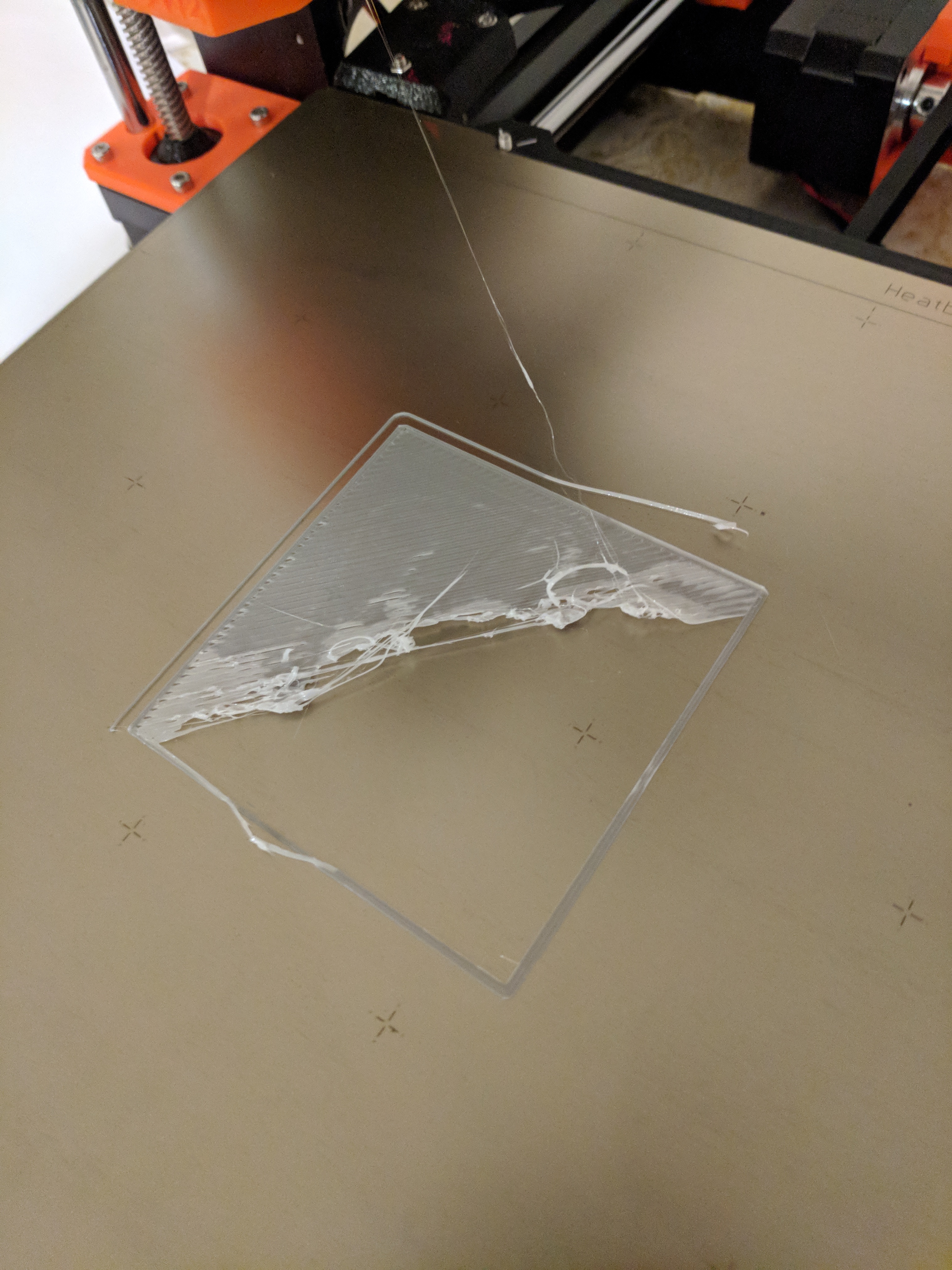
I really appreciate this adjust Z method. The stock method is impossible for me to tell the line height(maybe I'm too old with bad eyesight). And after giving me the below result, left me wondering if something was wrong with my printer(even Z -3k didn't help).

The same config on your test method. Nice thing about the below is it made it clear that where things were printing was correct, it just wasn't covering all the space.

The above basically falls apart the minute you pick it up. So some reading and a quick PIDA adjustment later:

Much better(Z 0 to 300-ish), but easy to tell it's still not there by touch:

The next try after some Z tweaking and it's a complete solid piece:

I didn't even know these printers were capable of that. Anyway, thanks for posting this.
Re: life adjust Z - my way
Mark: Looks good. Yeah man, that little square was printed too fast and too small for me to get any any useful information from it....
I have read thru all 42 pages of this thread more than once and it was the most helpful, and most understandable, method I found to figure out the live Z adjustment. The notes on the beeps were a very helpful warning to be prepared because they are LOUD!! 🙂 🙂 Thank you to the OP and contributors.
As a recap of what I found helpful in this thread are my notes are below for a summary if it helps anyone. If anything is found to be inaccurate, please let me know and I will edit since I do not want to lead anyone astray. I use example numbers for reference. Clearly, you should not use these numbers, as these are just examples for illustration as each printer is different and has different values but it illustrates the concept using info from this thread.
Live Z Calibration Notes
The sheet thickness begins at about 0.27mm when the nozzle is too high (probe too close to bed) e.g: <0.500> live Z value. There are splits/gaps/individual strands in the sheet and it is easy to remove from bed when too high. The nozzle needs to come down closer to bed, so probe needs to be raised away from bed (or live Z adjust more negative).
The sheet thickness is 0.20mm when correct z adjustment (Nozzle/ probe correct). e.g. <1.250> live Z value. The sheet is a completely smooth and homogenous glossy surface to the touch at the correct z adjustment. No gaps, no strings, no splits, just a single smooth sheet. For PLA, the desired thickness is 0.20mm. (I have never attained this, close, but not 0.20mm which I think will require a PINDA height adjustment, but that is for later).
The sheet thickness then rises again to approx. 0.23mm when the nozzle is too low (probe is too far from bed) e.g. <1.500> Live Z Value. The surface is dim and rough to the touch with wrinkles and spikes on it and fine strings. The sheet is very stuck to the bed. You can print items with the nozzle too low, but it is not optimal.
For example only – visual representation based upon <1.250> as the correct Z-Level.
<0.250> <0.500> <0.750> <1.250> <1.500> <1.750> <2.000>
_____________________________________________________________________________________________________________________
Nozzle too High / Pinda too low Correct Nozzle too low, Pinda Too High
Go more negative on Live Z Dialed Go more Positive on Live Z
Always measure the middle of the calibration square, not at the perimeters/edges because there are bumps that will throw off the measurement.
jb
Strange women, laying in ponds, distributing swords, is hardly a basis for a system of governance!
Re: life adjust Z - my way
Thanks for this thread. I am sure glad I have patience as I was able to print a ton of other stuff on other printers while I was trying to resolve my layer issues with the Mk3.
My Mk3 was a kit and the first time I tried setting it via the zip tie and it was still too far away from the bed. I also tested using a 1mm Dunlop Ultex guitar pick so I knew something was wrong. I ended up getting another Pinda v.2 as mine failed testing. I was sent a replacement and I swapped it out and tried again.
I was only able to get good adhesion+compression at -0.750. My digital calipers read .2mm when tested from the center.

My replacement Pinda's height was set at 1mm via the Pinda tool I printed here: https://www.thingiverse.com/thing:1977997
All you do is bring the nozzle down to the nozzle section of the tool and slide the sensor down. No guesswork. I am used to using sensors that have adjustment screws. Makes it much easier to get a perfect layer.
There really should be a 100% tested calibration tool included with the kit. It would save alot of time.
Re: life adjust Z - my way
Okay, so I managed to snap a picture. The top left keeps printing with gaps. My Live Z is currently at about -0.625. That seems to give me the smoothest print on the rest of the square, but no matter what Z setting, I still have those gaps. I've also tried messing with the bed level adjustment and doing -50 on all 4 points had zero effect on that area. I'm at a loss 🙁
Anyone have any thoughts on this? No matter what I adjust, I still get gaps from about the middle point to upper left. 🙁
Me too, same exact issue.
My print are very nice though.
Re: life adjust Z - my way
Anyone used this method to calibrate a nozzle with different diameter? I'm trying to do this with a 0.6mm nozzle and its just not cooperating.
Re: life adjust Z - my way
You need to slice your own versions for different nozzle sizes and materials. I've generated some gcode files for each size. I like to use:
Anyone used this method to calibrate a nozzle with different diameter? I'm trying to do this with a 0.6mm nozzle and its just not cooperating.
I've got a sample set for a 0.60mm nozzle on my nozzle sizes note page if you're interested. I haven't uploaded the sets for 0.20, 0.25, 0.30, 0.50, 0.60, 0.80 and 1.00mm yet but can try to get access to them if they'd be helpful. Note that I've got some pauses built-in to wait for the PINDA probe to warm up, issue quieter chirps and so forth, so don't be alarmed if it's slow starting up.
Thanks! I'll give it a go and report back.
Re: life adjust Z - my way
So the first few lines print OK before it starts catching. Can someone please help me identify what's going on here?