First layer from factory
Hi all
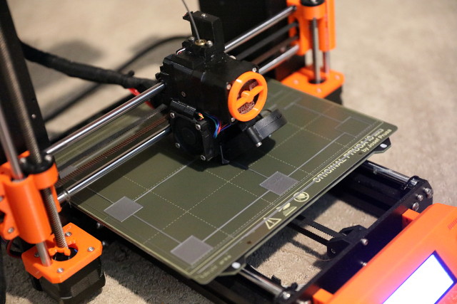
I bought a factory assembled i3 MK3S+. First thing I printed is the whistle from the samples (resized to 70% to save time), and luckily (or unluckily) I still own that piece.
But I detected some click noise on Y-axis when it has reached the maximum, so I decided to perform a fresh calibration. That has deleted also the first layer setting. The click noise went away, but I struggle to find the perfect first layer setting. And unfortunately since I am a noob, I didn't take a note of the first layer setting which it had from factory 😪
So I made myself familar with some videos and articles. I understand that the bar should not warp up and the lines needs to be without gaps etc. With every setting I was always also printing again the whistle and I compared the result with the one I printed with factory settings.
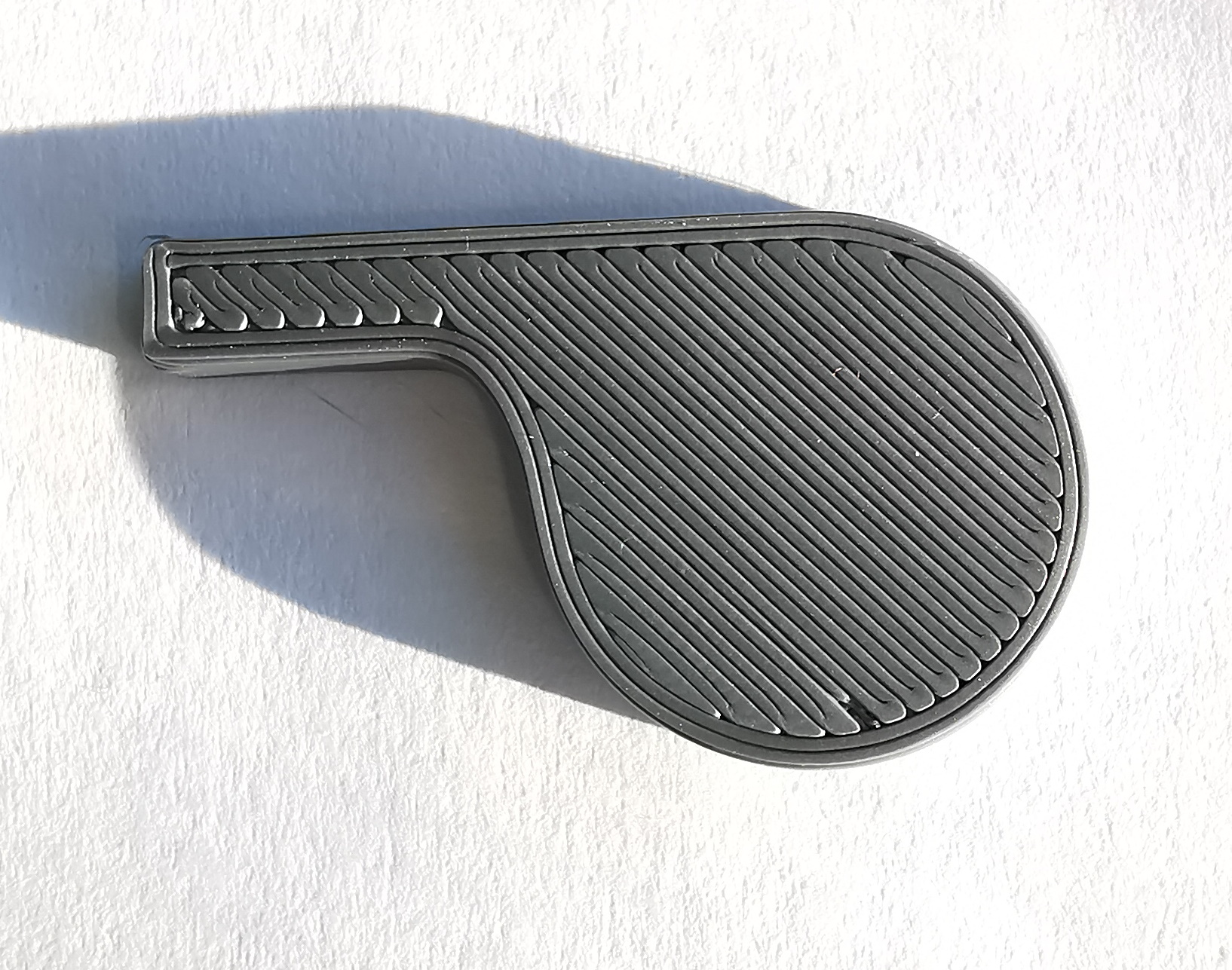
Here the picture of the whiste with factory settings. You can not see strings as such, they are melted together everywhere, between the lines and also when they connect the border.
My problem is now that the setting -1.100 has almost no warps as how it should be in theory (to my best knowledge), but no gaps between the lines on the sample. But the whiste looks much different, worse. You can see the strings clearly on the whistle, not melted together at all.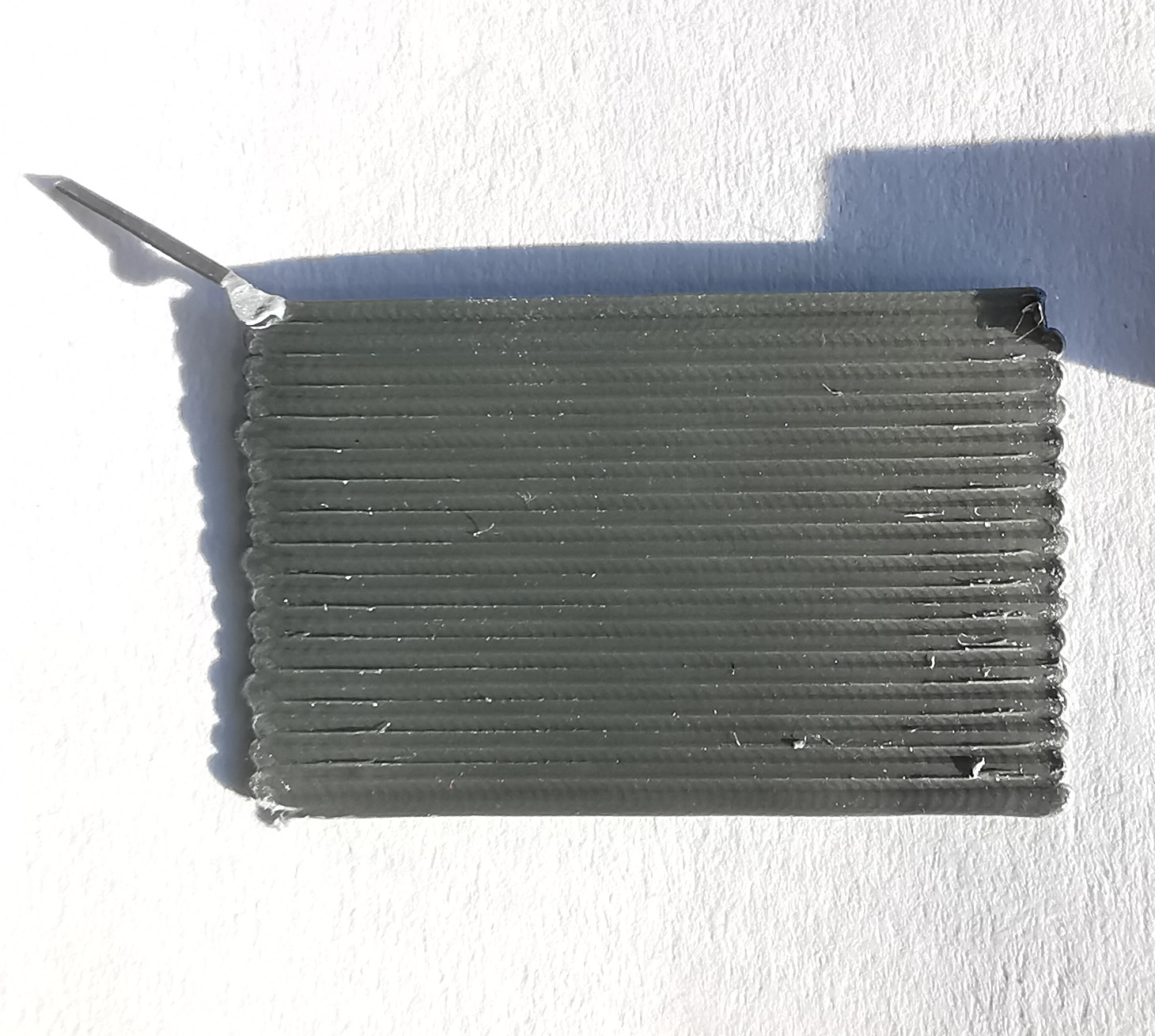
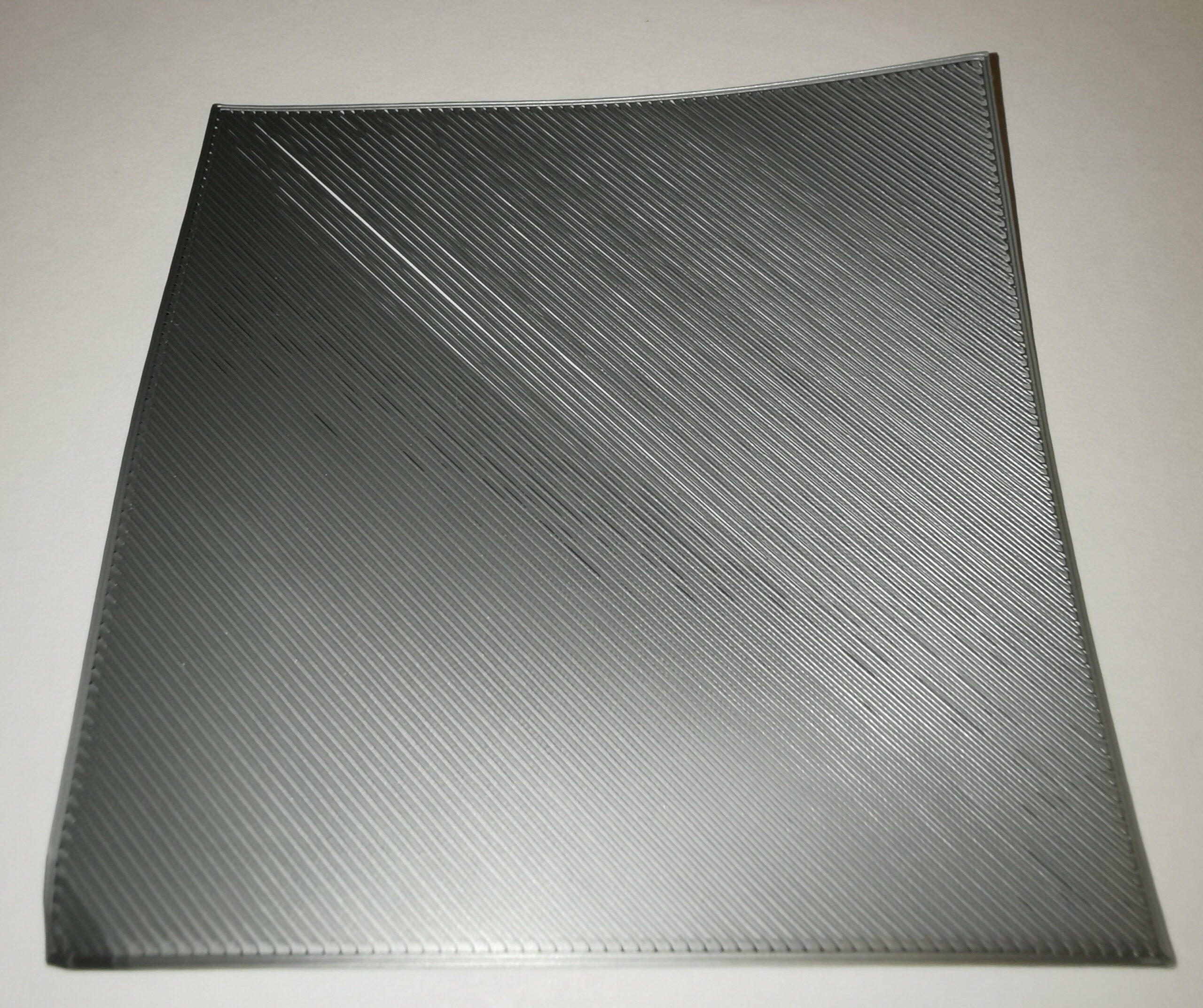
As soon as I start to choose -1.150 it starts warping up on the sample, so too low in theory. but the whistle looks a little bit more nice: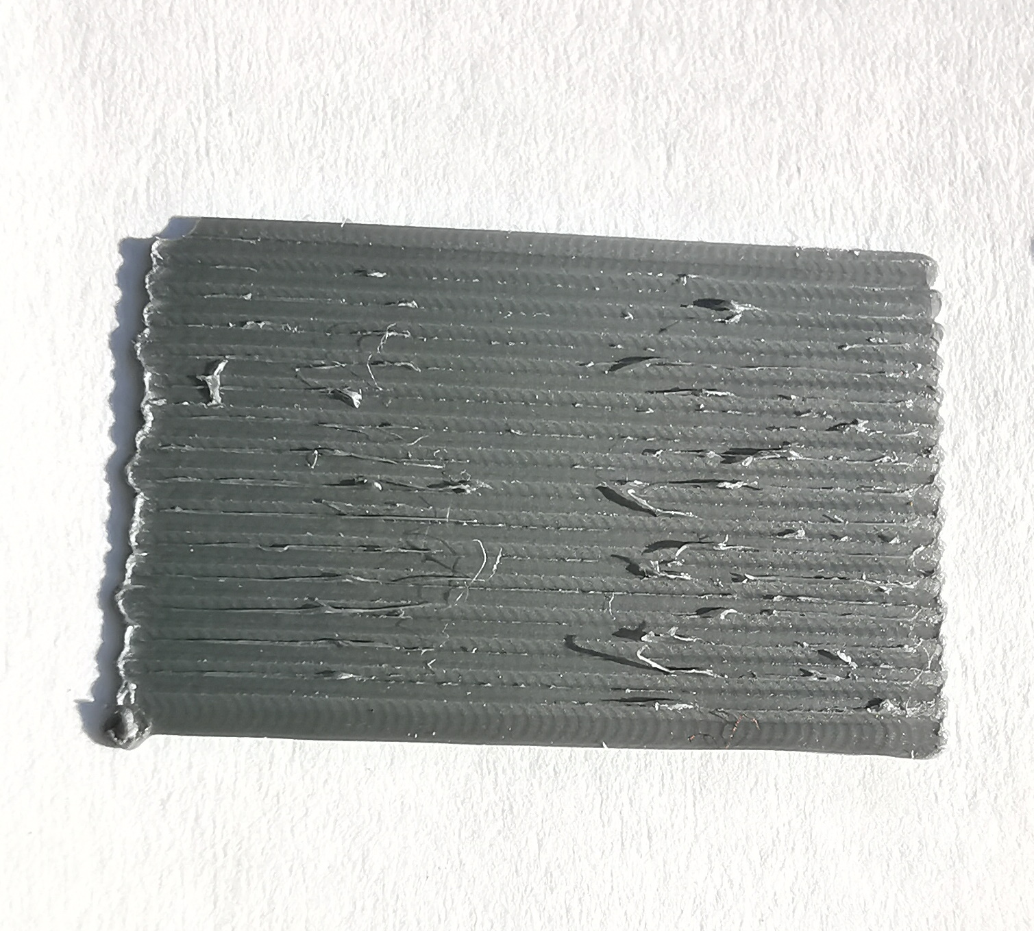
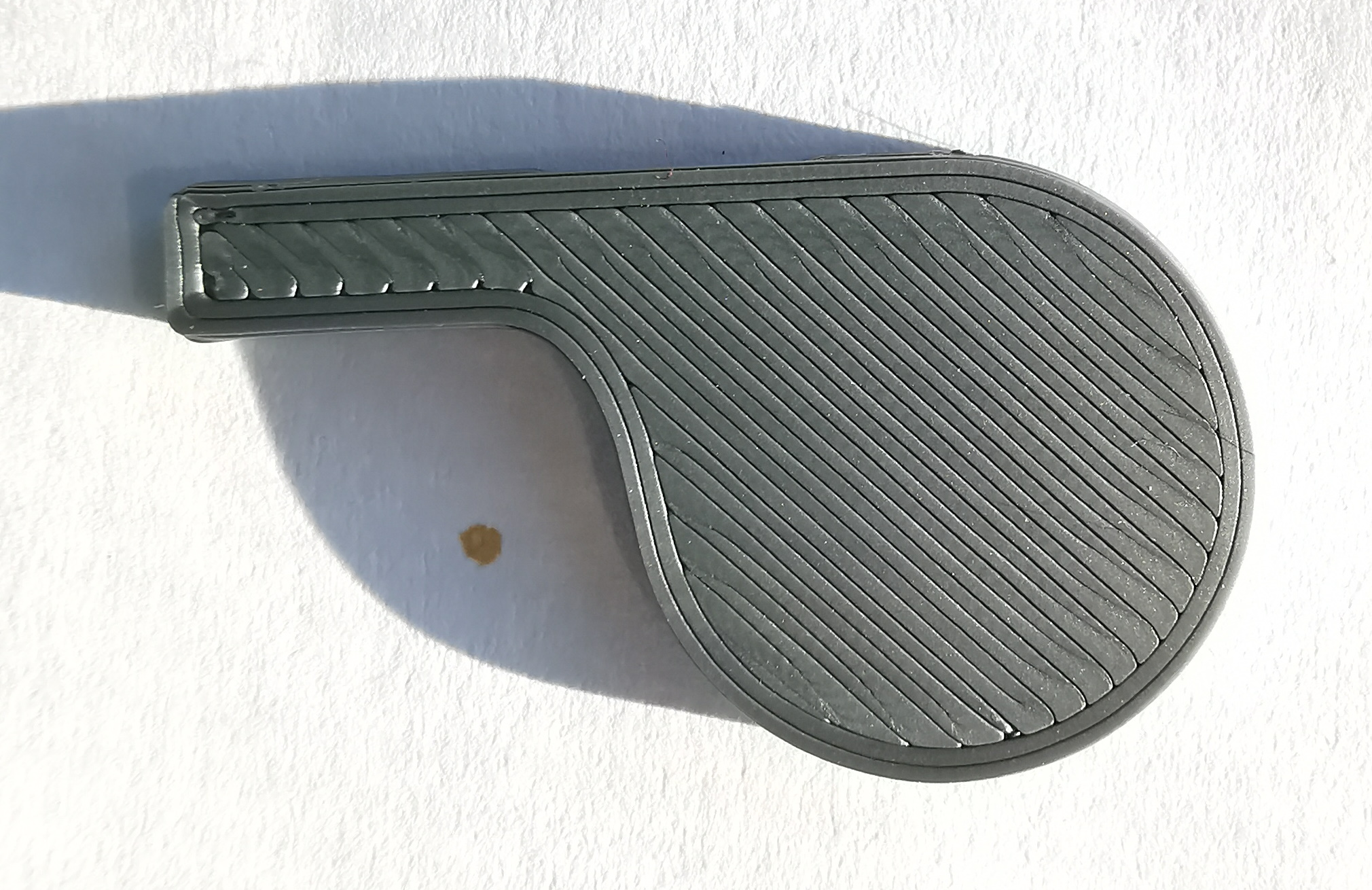
I also tried -1.175 and it comes much closer to the factory whistle and looks pretty nice. I don't have a picture of the sample, but it was warping up even more of course.
So I have now the dilemma that I'm not sure how exactly it should be. Should I strictly follow the test pattern and use -1.100 as it has no warping, but the whiste that does not look like the factory one?
Or can I go down a little bit to have a better visual real product by ignoring the fact it is warping up?
Was maybe the factory setting not good and hence I'm using a wrong reference?
Is there any risk for damage something or choking the nozzle in case of a too low setting?
Many thanks in advance.
I recommend you go by the first layer calibration and not the whistle.
-1.15 is too low. Using your best setting from the first layer calibration will give you optimum overall results for many different models. That second whistle is a good clean print and your printer is working well. I also got the factory assembled mk3s+. The offset on my printer turned out to be a bit too high and I am getting better results going a bit lower.
Mk3S+,SL1S
I might suggest that you try any of various one-layer calibration prints that cover the build plate.
These will give you a good idea of the overall Z calibration, as well as any left/right front/rear tweaks that may need to be made.
Further research
Thank you guys for your answers. In the meantime I'm 100% sure that I have some issues, as I made some interesting observations.
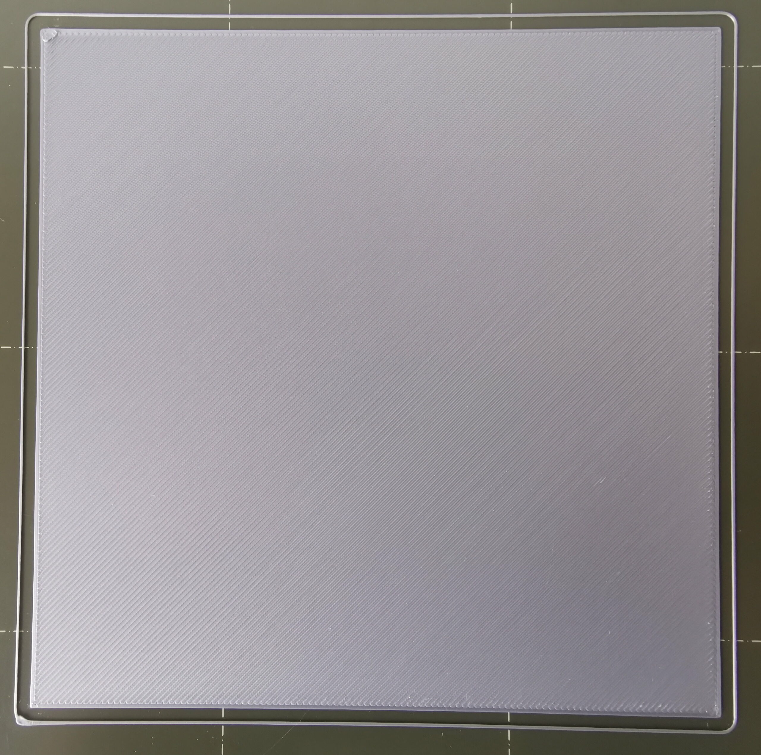
I printed a 75x75mm test square from a thingiverse bed level test suite, which got printed exactly in the middle of the steel plate.
The lower left side was fine, but the upper right side had gaps! hugh gaps.
So I changed the bed leveling measure from 3x3 to 7x7 and printed again, now it was having gaps everywhere.
Now I printed (from the same suite above) the 3x3 squares. It looks as it's exactly the one from your screenshot @jsw. The result as a table:
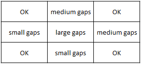
Even more frustrating, the corners are more or less OK, but the places between aren't, and the center (where most prints happen) is even worse.
But that somehow explains why the first layer test square looks ok, as it gets printed in lower left corner, while something printed in center isn't good.
Unfortunately with the advanced bed level correction I can just correct up, down, left & right. That is imho not good enough, as theoretically based on above finding I should increase the value on each position, but that will become similar to change the general setting, and it will affect corners as well.
For fixing that, should I just increase the general value until the center becomes perfect, with the consequences that the corners are too low (where I don't print often)? Are there other options?
That is progress.
If enabling 7x7 got you to a consistent bottom (large gaps everywhere) you should be celebrating. Throw the genetic results grid thinking out. You are making progress. You now have consistent nozzle height! Now lower it until the gaps fuse.
and there is no such thing as a factory setting
Get that thought (factor setting) out of your head. From the factory, the printer comes ready to calibrate. Not calibrated. There are too many variables - even humidity at your location can impact a good setup. The color of the filament can impact live Z. The brand of the filament can impact live Z. If your printer printed something after shipment (and you skipped or breezed calibration) then you are just lucky that 30 random factors fell into place for you.
I'm very surprised that they have not made the 7x7 probes the default. I've lost count of those who note improvement in print quality when switching to 7x7.
For the smooth sheet I suggest tuning things, a little bit at a time, for the best looking 'squish' factor, meaning the oval/ellipsoid profile of the deposited plastic that appears in the illustrations. I will sometimes use a spare 50mm camera lens as a loupe to inspect this.
For the textured sheet, however, I've gotten into the habit of tuning to the point where the 'brush strokes' just disappear into the textured pattern when viewed from the underside of the test print.
RE: More tests
Thanks for all the comments.
I made tons of test the last few days. But I did focus first on a 75x75 mm square in the middle and later with a 120x120 mm square. as this is the dimension I usually print. I've given up on the 3x3 squares.
At the end yesterday I achieved a very good result on the 120x120 mm square using the 7x7 bed leveling setting and -1.180. it warps up a bit on the calibration square, but I don't care as I usually don't print in this area. I hope it keeps stable now.
consistent
If enabling 7x7 got you to a consistent bottom (large gaps everywhere) you should be celebrating. Throw the genetic results grid thinking out. You are making progress. You now have consistent nozzle height! Now lower it until the gaps fuse.
I believe you misunderstood me. Moving to 7x7 has just made it consistent in the middle with the 75x75 mm square print. the corners of the plate were fine at this moment, but not left, right, top and bottom, and even not middle.
Somehow a progress, but not really how it should be.
With current lowering, I am able to have a 120x120 mm square fine. but I don't want to know how it looks like on the corners, there it will be too low for sure.
I'd call that good and move on