P.I.N.D.A. probe misaligned
Hi there!
I upgraded my original prusa i3 to the mk2 version this week-end. But I have a little issue with the PINDA probe.
From the various advices/tutorials/etc from Josef, the probe should be aligned like this :
However, mine is more like in the third case, a little off (see attachments below).
This is particularly obvious when doing the 9points calibration as the last one is totally missed.
I don't know what can cause this issue, if someone has an idea I would greatly appreciate it :).
Thank you in advance for any help!
Re: P.I.N.D.A. probe misaligned
Hi Wig,
This is a very common issue that can be fixed by fine-tuning the build of the printer.
Actually there are several factors and adjustment to consider to fix this, everybody have to make it once (excepted the very lucky one ^^).
To fix that, you should consider the Pinda position on multiple position on the heatbed, not only one. In fact, I consider that fixing the first 3 front positions should be enough to fix the 6 remaining positions.
Here is below 3 different issues that you can have:
Side shift:
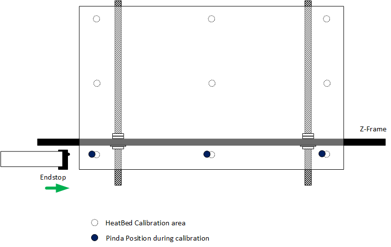
This one should not be seen often, due to the build design. But the End-stop can have a tiny side translation needed. For that you need to unscrew the screws holding the endstop, push the endstop on the proper position, and while holding it, screw it again.
Front shift:

This happen when the Z-frame is not positionned at the proper distance from the back of the Y-frame. To fix it, just unscrew the M12 bolts holding it, move the Z-frame back (or front, depending of the position of the pinda relative to the heatbed probe circles, and tighten it back. Be sure to maintain the Z-frame flat while doing that, so I recommend you to remove the 4 pads under each corners and to place a stack of papers or business cards below right and left side of the Z-frame during this operation.
Twist shift
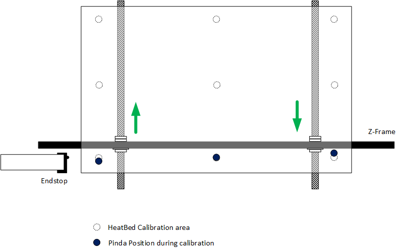
Probably the most common issue, and this is why considering a single pinda position is not helpful. This happened when each side of the Z-frame are not at the same distance from the back of the Y-frame, or if your Y-frame is not perfectly square.Like the front shift, just unscrew the M12 bolts holding it, move the Z-frame back (or front, depending of the position of the pinda relative to the heatbed probe circles, and tighten it back. Here again, be sure to maintain the Z-frame flat while doing that, so I recommend you to remove the 4 pads under each corners and to place a stack of papers or business cards below right and left side of the Z-frame during this operation.
Most of the time, you will have a combinasion of front shift and twist shift at the same time. Take your time to fix the alignments based on these explaination, consider this time as an investment, you'll be very happy after 🙂
I'm like Jon Snow, I know nothing.
Re: P.I.N.D.A. probe misaligned
Great explanations. The side and twisted pictures don't match the text though. Also, I tried pushing end stop sensor as far as possible but it is still misaligned slightly by the way.
Re: P.I.N.D.A. probe misaligned
Thanks for pointing it Prusayo, I fixed the mess 😉
Yes there is not a lot of margin for the endstop, and most likely you can easily make it miss the contact with the extruder holder, I ermember you had this issue. Did you reprint the extruder holder to fix it ? The very first mk2 delivered had some tolerance issues.
I'm like Jon Snow, I know nothing.
Re: P.I.N.D.A. probe misaligned
What a great set of diagrams and explanations christophe, this should be made part of the official Assembly Manual or 3D Printing Guide!! 😎
Re: P.I.N.D.A. probe misaligned
^^ +1. Fantastic explanation!
Re: P.I.N.D.A. probe misaligned
Thanks for pointing it Prusayo, I fixed the mess 😉
Yes there is not a lot of margin for the endstop, and most likely you can easily make it miss the contact with the extruder holder, I ermember you had this issue. Did you reprint the extruder holder to fix it ? The very first mk2 delivered had some tolerance issues.
I thought fw 3.04 was attempt to resolve this issue? I was waiting for official release before attempting. Why would extruder holder affect endstop sensor placement? I think I'm getting more confused now. I have never tried printing printer part yet either. I'm afraid I'd make it worse.
.
Re: P.I.N.D.A. probe misaligned
Yes FW should fix that, as it will be possible to change the pinda probe positions.
The extruder holder push the X-endstop with a small part. In the very first mk2 sent, there were some issue with sizes, I add to reprint it because the heater was not fitting well into the holder. There were some reports of users that had to add a little part of plastic on this small part to be able to properly trigger the endstop, and this may in some case add additional offset on the X-axis. Now everything is allright, sorry to confuse you.
However I'm glad my Visio drawing helps people ^^
I'm like Jon Snow, I know nothing.
Re: P.I.N.D.A. probe misaligned
The extruder holder push the X-endstop with a small part. In the very first mk2 sent, there were some issue with sizes, I add to reprint it because the heater was not fitting well into the holder. There were some reports of users that had to add a little part of plastic on this small part to be able to properly trigger the endstop, and this may in some case add additional offset on the X-axis.
I'm not sure what you mean by "extruder holder". Are you referring to X-carriage:
http://manual.prusa3d.com/Guide/3.+X-axis+assembly/105
(Step 2, red)
This printed part?
https://github.com/prusa3d/Orignal-Prusa-i3/blob/MK2/Printed-Parts/stl/x-carriage.stl
I checked extruder manual section but don't see a part that touches the x-endstop but may I'm misunderstanding something. Thanks.
Re: P.I.N.D.A. probe misaligned
Yes you're right, that's the part I was talking about.
I'm like Jon Snow, I know nothing.
Re: P.I.N.D.A. probe misaligned
The extruder holder push the X-endstop with a small part. In the very first mk2 sent, there were some issue with sizes, I add to reprint it because the heater was not fitting well into the holder. There were some reports of users that had to add a little part of plastic on this small part to be able to properly trigger the endstop, and this may in some case add additional offset on the X-axis.
This printed part?
https://github.com/prusa3d/Orignal-Prusa-i3/blob/MK2/Printed-Parts/stl/x-carriage.stl
Yeah, the little "L" part bottom right when you open that file online is the actual part that pushes the microswitch for x-end stop.
I couldn't move mine out much at all so I'm one of those who added some extra plastic to offset it a little bit, and now all 9 points are inside the circle and I'm printing happily 🙂
Re: P.I.N.D.A. probe misaligned
So I printed out the latest x-carriage stl from github and using digital calipers, do not see any difference in the length of the width containing the section that hits the endstop so I don't see how it would help to swap it out. The changelog for that piece is here:
https://github.com/prusa3d/Orignal-Prusa-i3/commit/71bbf84b3040a687bf6384ccfa3a90650a385550
I can't tell whether it's been made longer but the explanation is:
"Bigger bearing holes for easier assembly and fixed 2D manifold issues"
That doesn't seem like it's related to fixing the issue where the probe is off by 1-2 mm on the x-axis. It seems like a bit of work to swap it out as I'd have to cut off the zip ties and reinsert the black bands etc.
Based on the changelog can anyone confirm whether it would help with the probe being off slightly? The thing is, I'm not having a problem printing so maybe I'll just try the tape/cover trick to get the probe aligned perfectly or wait until the new 3.04 fw is available and deal with it that way instead.
Re: P.I.N.D.A. probe misaligned
Out of curiosity, I taped a 1mm pla rectangle to the L-section that hits the endstop and now the probe is directly in the circle. Calibration worked fine before, and it works fine now, so I don't see what the point was other than to have the probe perfectly in the circle.
Re: P.I.N.D.A. probe misaligned
Thank you Christophe for the awesome answer! (nice drawing from 'boulet' by the way ;)).
I had hints about the issues but the drawing along the explanation really helped me visualize it.
For that you need to unscrew the screws holding the endstop, push the endstop on the proper position, and while holding it, screw it again.
I tried to check that part but something bothered me. You cannot move the endstop that much and even though you can try to steal like 0.05mm of it, the screws will "bring it back" on track.
What I am trying to say is: the endstop (at least in my case) does not have the possibility to move in either direction of the x-axis. Apparently this was common in the first mk2? I will probably try the new beta FW in that case.
Thank you again for the great examples 🙂
Re: P.I.N.D.A. probe misaligned
After upgrading to the 3.0.4 beta firmware... I now have a perfect bed calibration :).
This is a really really nice feature, I love it!
Re: P.I.N.D.A. probe misaligned
Thanks Christophe for the very good explanation, but the heatbed of the MK2S kit has only circles at point 1 and 9.
What do you suggest to do for the P.I.N.D.A probe alignment?
Maybe you can do this:
1) Use "Auto home" from the LCD controller and do the adjustment you suggested, till the probe is in the middle of the circle at point 1.
2) Move the extruder on the X axis to the right, till the position of the expected point 3 (missing) circle. It can help, if you measure the distance of the point 9 circle and the right bed border and position the probe at point 3 at the same distance to the right border.
3) On point 3 measure the distance from the front bed border to the probe. If the distance is different from that on point 1, then do the adjustment you suggested.
4) Once that the the probe at the position of point 3 (missing) circle is correctly positioned (i.e. the distance from the probe to the front bed border is the same as in point 1 and the distance from the probe to the right bed border is the same as in point 9), move the extruder on the Y axis till the circle in point 9. If everything went well, the probe should be in the middle of the circle.
5) Use again "Auto home" to position the probe again on point 1 and check that the probe is still in the middle of the circle.
6) You have also to make sure that after all the adjustments, also the X-Y axis perpendicularity is still correct (see kit assembly manual chapter 7, step 19).
What do you think about this?
Re: P.I.N.D.A. probe misaligned
honestly how u suppose to move it, lets say its off, in your instructions you have written something about 100mm from the end is where the z axis brace should be, which is good, yet you have holes in the back bracket for the power supply to hook up to the z axis which also show how to hook it up. so should we just ignore the power supply hookup and measure the 100mm? its soo confusing, that was like the worst part of the assembly, everything else was very well written, but that part was like saying pick between door one and door two and the answer for which door is the right one is "yes".
thx
sonny
RE: P.I.N.D.A. probe misaligned
This is quite an old thread.. but i am not finding an answer to a presumably related issue i am having with my Mk 2.5S. I have quite a bit of side shift, (an entire Pinda diameter's worth) but there is essentially no adjustment in the end stop switch position (other than the screw-hole tollerance.. less than ~.1mm?). I would need a lot more adjustment for this to make sense.
Any other ideas to correct for a side shift misalignement of a pinda probe?
The printer worked great for a year +. After an upgrade to the latest printer head, this behavior started, and i cannot get past XYZ calibration. This is what mine looks like after an Auto-Home.

reference the only found advice that is the same as the 2016 entry in the second post: https://help.prusa3d.com/article/7W8CEH4CfU-p-i-n-d-a-probe-misaligned
RE: P.I.N.D.A. probe misaligned
In the 2.5 upgrade kit there is a small part which extends the extruder to connect with the end stop switch.

Bill
Tagaytay City, Philippines
Founder member of Philippines Prusa Printer Owners FB Group
Sponsor Pillars of God Academy in Bacoor
RE: P.I.N.D.A. probe misaligned
In the 2.5 upgrade kit there is a small part which extends the extruder to connect with the end stop switch.
This appears to be my issue. Thanks very much for the help!