MK2 Rambo pin available for LED control w/ Gcode?
In this video by Tom, he shows how to use a spare pin to control a led using Gcode commands w/ the stock firmware
I want to turn on a LED when the nozzle temp hits 180C which is when I can load filament
Is this possible using the stock configuration of the MK2 if I am not using the MM kit? Which pin would be the best?
Re: MK2 Rambo pin available for LED control w/ Gcode?
In this video by Tom, he shows how to use a spare pin to control a led using Gcode commands w/ the stock firmware
I want to turn on a LED when the nozzle temp hits 180C which is when I can load filament
Is this possible using the stock configuration of the MK2 if I am not using the MM kit? Which pin would be the best?
Hi David,
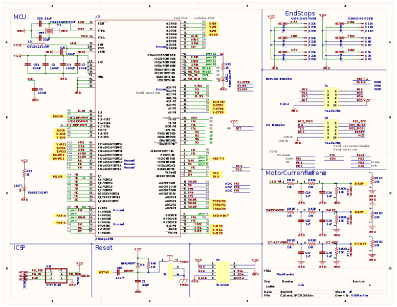
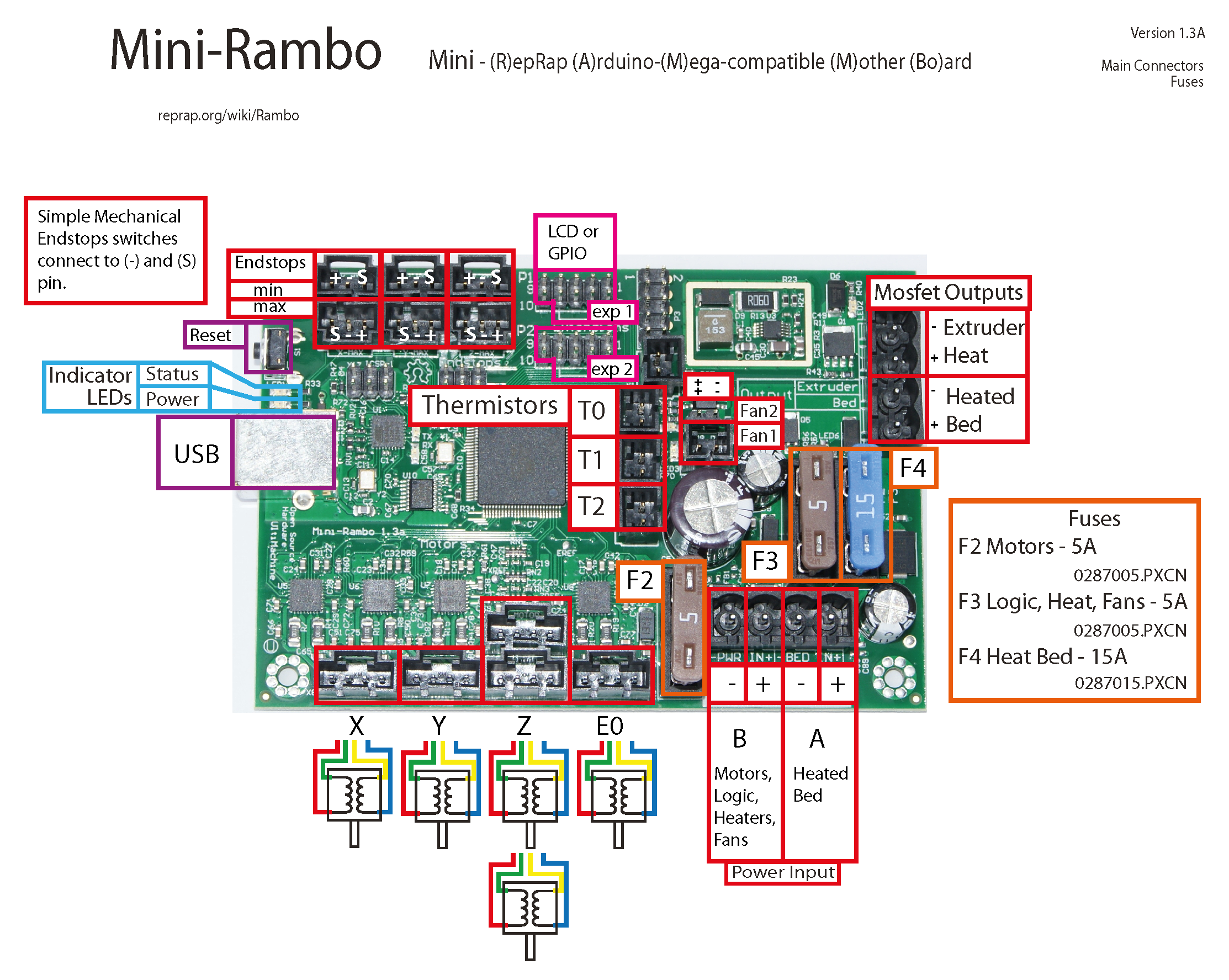
checking the assembly manual https://d17kynu4zpq5hy.cloudfront.net/igi/prusa3d/UZGtDxDLODaR2e5q.huge and miniRAMbo schematics http://reprap.org/wiki/MiniRambo you can see that there are few unused pins:
- x-max (VCC, 30, GND)
- y-max (VCC, 24, GND) (i will use it for Filament runout sensor)
- z-max (VCC, 23, GND) (i think about using that with two switches in serial as real Z-endstops on the top)
- P3 pin 1(VCC), 3(TX2 or arduino pin 17), 5 (RX2 or arduino pin 16), 7 (GND) are used by the Multi material upgrade, so better not to use it.
- P3 pin 2(VCC), 4(GND), 6(SCL or arduino pin 21), 8 (SDA or aruino pin 20) (i will use these for I2C devices in the future)
- P3 pin 10 (PH2 or arduino pin 84) but it is also used on P1 pin 1 which connects to the buzzer on the LCD screen.
Using P3 pins 6,8 makes I2C possible to attach much more devies or salves doing the work.
So there are not a lot of populated pins left to do fancy stuff 🙁
Hope i can get the I2C bus running to get an ESP8266 or esp32 to do fancy stuff.
Hope that helps.
So for mi
Re: MK2 Rambo pin available for LED control w/ Gcode?
Cool, thanks for the info.
So are those the pin headers located next to the end stop plugs?
For ref:

Re: MK2 Rambo pin available for LED control w/ Gcode?
Nice example of controlling RGB w/ I2C:
Simple bridge between Marlin's BlinkM RGB LED output and a Neopixel (compat) strip.
https://github.com/c-/marlin-neopixel-bridge/blob/master/ATtiny85_BlinkM_Neopixel_Bridge/ATtiny85_BlinkM_Neopixel_Bridge.ino
This would require flashing the MK2 firmware so I think I will write code to get the PWM value to do other stuff so I keep the MK2 stock.
I've used the PWM source code in the past and it works well:
https://github.com/kiuz/PPM-Signal-Reader-ARDUINO/
Here is a sample of reading a PWM value from the Rambo:
#include <PPMrcIn.h>
// must be install into libraries http://github.com/kiuz/Arduino-Statistic-Library
#include <Statistic.h>
//init a Channel class to store and manage CannelX form reciever
Channel channel1;
void setup() {
Serial.begin(9600);
Serial.println("Ready:");
pinMode (13, INPUT);
channel1.init(1,13);
}
void loop() {
delay(20);
channel1.readSignal();
Serial.println(channel1.getSignal());
Serial.println(channel1.getPosition());
Serial.println(channel1.getVersus());
Serial.println(" ");
}
Re: MK2 Rambo pin available for LED control w/ Gcode?
checking the assembly manual https://d17kynu4zpq5hy.cloudfront.net/i ... R2e5q.huge and miniRAMbo schematics http://reprap.org/wiki/MiniRambo you can see that there are few unused pins:
- x-max (VCC, 30, GND)
- y-max (VCC, 24, GND) (i will use it for Filament runout sensor)
- z-max (VCC, 23, GND) (i think about using that with two switches in serial as real Z-endstops on the top)
- P3 pin 1(VCC), 3(TX2 or arduino pin 17), 5 (RX2 or arduino pin 16), 7 (GND) are used by the Multi material upgrade, so better not to use it.
- P3 pin 2(VCC), 4(GND), 6(SCL or arduino pin 21), 8 (SDA or aruino pin 20) (i will use these for I2C devices in the future)
- P3 pin 10 (PH2 or arduino pin 84) but it is also used on P1 pin 1 which connects to the buzzer on the LCD screen.
Using P3 pins 6,8 makes I2C possible to attach much more devies or salves doing the work.
So there are not a lot of populated pins left to do fancy stuff 🙁
Hope i can get the I2C bus running to get an ESP8266 or esp32 to do fancy stuff.
Hope that helps.
So, If I understand you correctly, utilizing all you plan to. The only controllable pins left are the X-max (30), and P3 pin 9 (not sure on arduino call out), and possibly Z-max (23). Is that correct? While I doubt I2C is in my future (but you never know), I do think for myself leaving openings for Multi-material upgrade and Filament runout sensor are good ideas. So far (only a few weeks old), I haven't seen the need for a Z-endstop either in synchronizing motor position , or in concern for height, but I'm still very green, so that may be another usable pin for myself.
I think like many of us, after seeing Tom's video on adding lights this weekend, it does seem like something to look into.
Re: MK2 Rambo pin available for LED control w/ Gcode?
For ref:
Re: MK2 Rambo pin available for LED control w/ Gcode?
So, If I understand you correctly, utilizing all you plan to. The only controllable pins left are the X-max (30), and P3 pin 9 (not sure on arduino call out), and possibly Z-max (23). Is that correct? While I doubt I2C is in my future (but you never know), I do think for myself leaving openings for Multi-material upgrade and Filament runout sensor are good ideas. So far (only a few weeks old), I haven't seen the need for a Z-endstop either in synchronizing motor position , or in concern for height, but I'm still very green, so that may be another usable pin for myself.
I think like many of us, after seeing Tom's video on adding lights this weekend, it does seem like something to look into.
Hi Steven,
You can use all listed pins as you like, it is up to you. But i think it makes really sense not to use the MM used pins.
I just colored some in because of MY plannings to do.
If you check the schematics you will see that P3 pin 9 is RESET and already used in several different locations like P2 pin 8.
Re: MK2 Rambo pin available for LED control w/ Gcode?
For anyone going the I2C method, you can pick up these devices that can be re flashed using arduino ( http://chaozlabs.blogspot.de/2015/08/esp8266-in-wild-wifi-led-controller-hack.html ) for around $12.
For $12 dollars you get a ESP8266 with 5 mosfets for driving LEDs. You can have Red, Green, Blue, warm white and cool white.


Re: MK2 Rambo pin available for LED control w/ Gcode?
I've been doing some research on this as well. There aren't many pins on the MiniRambo not in use that are firmware controllable (not being used as an input only). You could tap into the X Y or Z Max end stop pins since they aren't being used and these are able to be GCode driven without having to modify the firmware.
The IRF520 which Tom shows in his video will hold the primary load since you are wiring the Power for the driver directly from the power supply and the driver is acting like a relay in that it just needs to see the MiniRambo sending a signal to tell the driver how much power to allow through. I'm planing on using an RGB LED strip which means I'll need three of the IRF520 drivers and I will probably be using all three of the Max Endstop pins to do this since I don't intend (currently) to wire in a filament run out sensor (which I currently do have one from Dyze Design) since I'd rather not mess with the firmware only because if Prusa is possibly going to keep updating it I don't want to have to constantly have to re-enable the runout sensor and its pin and reflash the board.
Re: MK2 Rambo pin available for LED control w/ Gcode?
The more I think about it, the more I think I'm just going go down the ultra simple path, and just hook white LED's to the power supply. My main interest is in visibility, not notification (although that is cool). I also turn off my machine when not in use, so the light's wouldn't be on all the time anyway, just when I'm using it. I know not everyone does this, and so I can appreciate wanting to have the extra control. But for me I think KISS will win out in this situation.
But, I still think Tom did a great job getting many of us thinking about what we can do with not too much work.
Re: MK2 Rambo pin available for LED control w/ Gcode?
So I think for my use case I will use the x, y and z end stop pins.
I am not looking for full brightness. I just want to have color change states for the following:
-Bed has reached target temp
-Nozzle has reached target temp (so I can switch out filaments)
-first layer is complete ( I always stick around until the 1st layer is down)
-Nozzle temp has cooled down below 65C
-Bed has cooled down below 30C ( I often print objects that will take two sessions to print all the required parts)
LEDs strips are 12V, the rambo is 5V. I may also go the route of using the cheap 2 pin diode RGBs or maybe the a single 4 pin all in one RGB.
I should use a mosfet to be super safe but would it be risky to do the following?
- Use a single led for each color.
- use a standard 3 wire servo bundle with a large limiting resistor inline to each of the LEDs
On another note, if Prusa could offer such a kit I would probably buy it (even though shipping would tack on $40 to the final price) because for me time is always the resource I am short of. Would so cool if you could get the MM kit completely built from the factory for this same reason.
Thanks for any feedback or thoughts,
Dave
Re: MK2 Rambo pin available for LED control w/ Gcode?
For anyone doing this kind of work, you can now pick up a fully assembled digital oscope for $20:
DSO 138
https://www.amazon.com/gp/product/B06XT6K6CF/ref=oh_aui_detailpage_o03_s00?ie=UTF8&psc=1

Re: MK2 Rambo pin available for LED control w/ Gcode?
Looks like these pins have been use for the Dyze run out sensor:
The question is are these pins GCODE enabled in the stock MK2 firmware?
Hi david.b14,
check this out for filament runout sensor http://shop.prusa3d.com/forum/improvements-f14/system-that-allows-to-stop-printing-automatically--t5006.html
I changed the FR_SENS pinout to y-max.
Re: MK2 Rambo pin available for LED control w/ Gcode?
Hi,
I have just completed the implementation of a LED controlled by the X-MAX pin available on the RAMBo Mini board.
As previous posts have mentioned, I had to change the source code in the firmware, compile it, and upload it to the 3D-printer, but is was quite easy. I just had to change two lines, so this is a change i happily make whenever I need to update to the latest firmware.
I made this change in the file Pins.h:
#define X_MAX_PIN 30
to
#define X_MAX_PIN -1
You will need to make this change two places in the file to make sure it's valid for both versions of the RAMBo board.
Just reply to this thread if anyone needs more detailed information on how to obtain the source code, compile it etc.
Regards,
Erik
Re: MK2 Rambo pin available for LED control w/ Gcode?
Hi,
I have found a pin very easily accessible and not used by the firmware.
It's pin PC5 of the Atmega, named 32 on arduino.
This pin goes to IO extension header P2 pin 10

this header connects to the LCD panel Header 5X2 pin 10 (close to the reset pin)
see schematics here : http://reprap.org/mediawiki/images/7/70/Controller_final_reprapdiscount.pdf
you can easily solder a wire on the connector pins
On the following picture, it is the big black connector on the right, and the top right pin
On the same row, the pin close to the connector is ground (it's not visible on the picture)

You can access this pin via Gcode with the original Prusa i3 MK2s firmware :
M42 P32 S255 to switch ON
M42 P32 S0 to switch OFF
JP