Monoplexer and Multiplexer Redesigns (no metal parts required)
I've gotten a little attention from various people for these parts, so I figured I'd give it a new topic. If this picks up some popularity and some more people test it, maybe it will even get a sticky some day.
So first off, I'd like to preface this post with why I decided to do these designs. My Multi Material upgrade (MMU) had problems within a week or two of assembling it. I did some research and I wasn't the only one having problems. I'll save you the long story, but essentially the feed paths in the original design combine in the multiplexer in a bad way. It creates a weak point due to the widened paths for the steel tubing. If you look at the picture below, you can see holes between the feed paths in the original design.

My redesign gets rid of the extra diameter of the feed paths by getting rid of the steel tubing. It also gets rid of the press in brass fittings. The idea is for more convenient replacement of parts since you don't need the press in brass fittings or the steel tubes. The only thing you need is the Festo fittings from the MMU, they thread directly into the plastic of this redesigned multiplexer. As you can see from the picture below, there are no holes between the feed paths.

Another advantage of doing an all plastic feed path is that it will "break in" over time, allowing for less resistance in the feed path as it gets used more.
I've also designed a single feed path design as an emergency backup to the multiplexer. This Monoplexer appears to have less issues than the original build or the MMU upgrade. I personally plan to use it for printing of parts when the Multiplexer goes down, but it could also be used as a permanent downgrade or just for printing single color models.
Here is the Monoplexer STL:
https://www.thingiverse.com/thing:2736405
Here is the Multiplexer STL:
https://www.thingiverse.com/thing:2740929
I've used the Monoplexer for multiple prints with no problems, the Multiplexer I've only done one print, but it worked well.
I'd really appreciate some feedback if anyone goes this route. I have one or two things I'd like to add in the future, but before I put a bunch of time into redesigns, I'd like to make sure it is something people will use.
Hopefully this is a little less stressful than the other fixes people have been going through. I love the MMU, I just always wanted it to be a little more user friendly in the maintenance point of view.
Any feedback is appreciated, thank you!
Re: Monoplexer and Multiplexer Redesigns (no metal parts required)
Thanks for designing these parts Seth. Definitely these openings in the combiner don’t seem ideal.
- how did you judge that these are the cause of a problem?
-don’t you think that not using the metal tubes will cause wear and not your described ‚break-in‘ ?
-what settings did you use for the print?
-Material =PLA?
Best regards and Happy New Year
John
Re: Monoplexer and Multiplexer Redesigns (no metal parts required)
Just saw your other thread Seth, the explanation is clear and well concluded.
Still I‘m unsure whether you have more wear when not using the metal tubes.
I‘m curious to hear more about your experience with your design.
Re: Monoplexer and Multiplexer Redesigns (no metal parts required)
Just to be clear, this is the correct printing orientation.
Re: Monoplexer and Multiplexer Redesigns (no metal parts required)
For the original, yes it is the correct print orientation, for mine, no it should be printed with the Input paths facing toward the print bed.
My fear was that with that much overhang in the middle of the multiplexer where the paths combine, it may skew it one way or another to a specific feed path while printing. That's why I print it in a vertical orientation, so there is less warping (my original part has an ovular output path for instance).
Just saw your other thread Seth, the explanation is clear and well concluded.
Still I‘m unsure whether you have more wear when not using the metal tubes.
I‘m curious to hear more about your experience with your design.
Only time will tell but if wear was too much of an issue then it would happen in the output feed path of the original multiplexer would it not?
The break in I'm describing is due to the layer "rings" that appear when printing. It makes very small ridges that will smooth as you use the part due to the ridges imprinted on the filament during extrusion.
It may wear out over time, this is mk 1 of this part after all. Worst case scenario is you print another and it's still easier to replace than the original.
And yes, it is all PLA.
I judged that the cause of my problem was that weak point a few different ways. One, I got a terrible jam that I couldn't push out in either direction and it partially blocked 2 of my other feedpaths but left the last one somewhat useable. This indicated a larger failure than a simple single feedpath jam obviously.
I can shine light down the paths well enough to see that one is completely blocked and there are "splinters" in two other paths.
When I sliced the original multiplexer and found that there were holes between the feed paths due to the extra width to account for the steel tubes, I connected the dots.
Once I have a few prints under the new multiplexer's belt, I will cut apart the original and confirm it.
I think I addressed all the questions, but let me know if I left anything out 🙂
Re: Monoplexer and Multiplexer Redesigns (no metal parts required)
Got a couple pictures to prove it's working lol.
Sorry for the blurry photo, my phone doesn't take great moving pictures.


Re: Monoplexer and Multiplexer Redesigns (no metal parts required)
the design i made is just like yours but what i did is the ports are larger to fit ptfe tubes all the way. on the output port same thing fitted with ptfe tube and i have had zero plugs. now what i have is a bad extruder motor unable to push filament when working for a while. Seems i got junk parts..
Re: Monoplexer and Multiplexer Redesigns (no metal parts required)
Sorry to hear that, Ive had similar issues but luckily mine has mostly been printed parts I can redesign. I've done two 5ish hour prints with the multiplexer now and had no issues so I'm feeling good for now.
Re: Monoplexer and Multiplexer Redesigns (no metal parts required)
Thanks Seth for your detailed reply!
Your prints look also awesome. My original MMU multiplexer part works fine so far for a couple of models, except one layer failure in one of the downloadable models I've tried. See the missing white layer at the belly of the bear:

It might have been caused by the issue you describe.
Re: Monoplexer and Multiplexer Redesigns (no metal parts required)
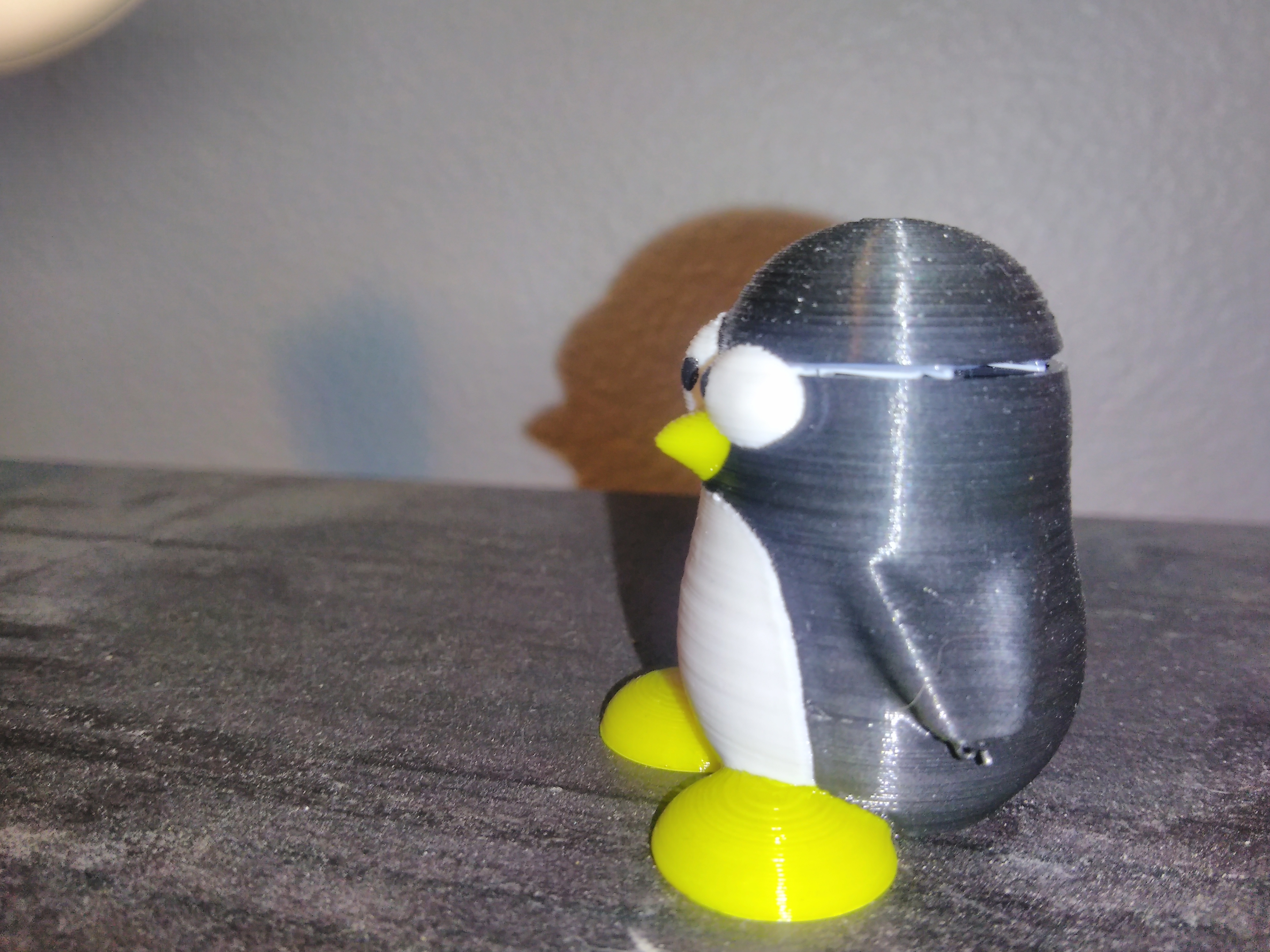
Same EXACT problem I had with my first multicolor printed penguin. I still have it actually, I will post a pic when I find it. At first I thought it was from the file but after the problems I had I'm not sure anymore.
Re: Monoplexer and Multiplexer Redesigns (no metal parts required)
I was under the impression that the steel tubes were to allow for cooling and forming the end of the filament as it's being extracted...it sure is annoying.
I'm wondering how your system will work after hours and hours of printing (that's often when issues start to arise: after unexpected wear over a long time)
That said, I'm printing your part next. 😉
Re: Monoplexer and Multiplexer Redesigns (no metal parts required)
If I'm looking at this from an engineering standpoint, the steel tubes are not for cooling. There is nowhere for the heat to dissipate so it makes little sense.
The filament should be cooled in the heat break where there is a fan blowing cool air over the metal fins (lots of surface area for heat transfer). By the time it reaches the splitter the filament should already be formed and cooled.
If I had to guess, the steel tubes were to eliminate feed path resistance, but it didn't work because the paths all still combine in PLA and for the reasons I've already mentioned with the weak points.
I have another thought but I will leave it for later when I get a good picture to help explain it.
Re: Monoplexer and Multiplexer Redesigns (no metal parts required)
Hi seth.g2... i like your redisign... but with your permission i'm doing some mods...
print in natural pla (almost transparent) and cut a little to better view whats going on inside...
testing right now...
when i load filament, it reachs level "a", and the prime extruding line makes it reach the hotend...
a little jam the very first attemp, but after drill the hole a bit... seems it works..
EDIT:
when the print job ends... the filament is retracted again to level "a"...
and the next job starts in the same condition of the first one...
and it works... six good jobs in a row... unbelievable but true... 🙂
you can view the modified monoplexer here:
https://www.tinkercad.com/things/lNcOGkD5uFy-plexermono-based-on-sethg2
i hope tonight i'll modify your multiplexer to view inside and print in natural pla...
Re: Monoplexer and Multiplexer Redesigns (no metal parts required)
the steel tubes in the multiplexer, are the secondary filament shaping location (originally intended to be the primary location), but the development team found that it was better to use the PTFE tube as the primary re-shaper. however PTFE is not a good conductor, so there is very little cooling in the ptfe. the steel tubes in the multiplexer are supposed to finally chill the filament end...
in the diagram below,
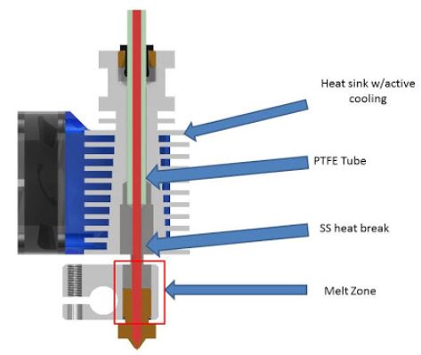
the PTFE tube is about 1.9mm ID, below that is the stainless steel tube which locates the PTFE in relation to the extruder and stops it getting near the hot part, preventing it from overheating when used with the more exotic high temperature filaments, this stainless steel tube has a sharply reduced section, to give a sharp transition (heat break) from the cold end to the hot end, reducing the heat transfer into the cold end.
whilst the bore of the stainless steel tube is supposed to be polished during manufacture, it is not an ideal place to reform the filament,
I believe this is where the plug forms on the filament, when excessive retraction is used...
the stainless steel heat break assembly has a larger ID than the ptfe tube, and if a plug forms there, it is difficult to move it either up or down,
I hope this helps...
under ideal conditions the stainless tubes in the multiplexor don't have a lot to do... as conditions move away from ideal, the tubes become more important.
regards Joan
I try to make safe suggestions,You should understand the context and ensure you are happy that they are safe before attempting to apply my suggestions, what you do, is YOUR responsibility. Location Halifax UK
Re: Monoplexer and Multiplexer Redesigns (no metal parts required)
Thanks Seth for your detailed reply!
Your prints look also awesome. My original MMU multiplexer part works fine so far for a couple of models, except one layer failure in one of the downloadable models I've tried. See the missing white layer at the belly of the bear:
IMG_0171.jpg
It might have been caused by the issue you describe.
Here is the Penguin I first printed with my MMU. The issue is EERILY similar to what you experienced.
Now that I've got that off my mind, I'll go ahead and continue my thoughts from earlier.
First off, thank you Joan for your diagram! I'm a big fan of visuals, and I think this makes it much easier to understand. I would like to bring up one extra point because it's not 100% mechanical design that achieves all of this magic, there is some clever programming as well. When the printer switches colors/uses the wipe tower, if you pay close attention, you'll notice that it sits and wipes for a bit without loading or unloading filaments (it is still the last color it was using in the hot end). Since I was not on the engineering team, I'll have to guess why. If I had to wager, I'd say it is so that the filament that is currently loaded either melts in the hot end and oozes out, or cools and shapes in the heat break (essentially giving the currently loaded filament a shape before it loads back into the splitter). I can tell you that when I unload my filament without the steel tubing in the splitter that they look completely fine. I have no globs, it has a conical tip just like you'd hope for.
Secondly, I'd love to see my design in transparent filament! You're welcome to make changes, we're part of a community that helps each other, and I think any improvements would be welcome.
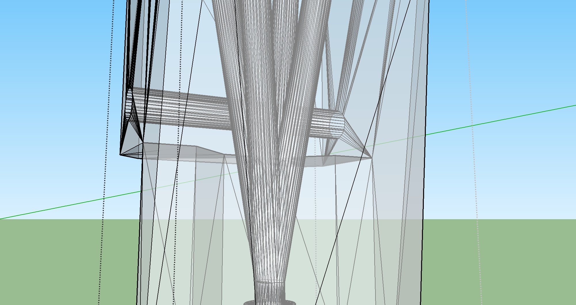
And now I'd like to get into a little more detail with the designs themselves, pictured below is an xray model of the original splitter.

Before I move on I'd like to discuss what I see and what I've learned thus far with this design. A lot of people seem to have trouble visualizing the inside of the splitter, so I hope this helps. First off, note the wider feed paths where the steel tubes are and how they touch at the bottom of the widened paths. This is where the holes are created that I've mentioned earlier. If you visualize the space between all of the feed paths, it makes a bulbous end with holes between them, which is where I think the weak point is.
Next I'd like to point out the path after the steel tubes. It has a section that narrows, which is fine, but the highlighted blue section is what I'd really like to talk about. This section is how I originally designed my model, in fact, I just deleted the upper portion of the model and continued the existing smaller paths all the way to the top of the model. If you've been following my posts on this topic and on the last, I have mentioned at some point that I had trouble with one of my prints. This is the point I had trouble. Basically when I extended these highlighted paths to the top of the multiplexer the filament wouldn't fit through the path at all!
I attributed this to a "layer stacking effect" where the ridges in the print make the path smaller. There is one other factor that was eluded to in an earlier post in which someone asked the correct printing orientation of the multiplexer. Prusa prints theirs on the side, whereas I print mine on the end upside down. I think this is why my paths may not have been "quite" as wide as the original. However, I think if you look at the shape inside the four feed paths that would have to be printed with an overhang and essentially suspended in space, it will have problems printing. I know I've had more problems with less complicated shapes only accounting for the overhang. And then there's warping!
This is where I'd really like to stress what I find to be the design flaws in the original design:
-Sideways printing (possibly leading to warping and overhang issues)
-A weak point where there are holes and strings holding an important shape (compounded by the first problem)
-Too narrow a feed path for the combined portion (the blue spot in the xray view)
I personally don't think cooling factors into this too much, I really think it's just the feed path's having too much resistance. What happened to my splitter appears to be a breaking of the bulbous "arrowhead" shape between the feed paths that partially or wholly blocked 3 of my feed paths.
Next I'd like to talk about what I did to change these problems in my design, some of which has been eluded to in other posts.
Below, is an xray view of what I designed. The first thing I want to mention is that it is not the same diameter feed path as the original is printed with. I did have to widen my feed paths in order to get a printable result.
This design takes care of the original design flaws in the following ways:
-Vertical printing to ensure consistent feed path diameters and less warping
-No holes between the feed paths, this makes it to where the "tip" between the feed paths gets gradually smaller instead of having a bulbous "arrowhead" like shape.
-Widened feed paths to reduce resistance and allow for unobstructed feeding of filaments.
I've had multiple people bring up the "wear" factor that seems to be a drawback in my design. Time is the main thing that will determine whether this is a real problem or not. This is, after all, a prototype replacement part. I would also like to mention that there is plastic feed paths in the original multiplexer, and that if wear is a problem, it would also be a problem in the original part.
I'm really sorry for the long post, but I wanted to address a lot of questions and concerns all at once.
If you do print these, please read the printing instructions carefully.
Thanks again!!
Re: Monoplexer and Multiplexer Redesigns (no metal parts required)
I'm really sorry for the long post, but I wanted to address a lot of questions and concerns all at once.
If you do print these, please read the printing instructions carefully.
Thanks again!!
Thanks for all this effort and for sharing your work. I really hope Prusa is listening, given the problems some people have reported. I've got a MK3 MMU on order for whenever they start shipping, and it would be great if they can incorporate some of your ideas.
Thanks! I take that as a great compliment.
I think that it is a little too soon to incorporate it into the kits, after all I only finished the design a few days ago and it needs to be fully tested!
I appreciate the attention it's been getting though.
I can tell you that I have definitely been getting good results over the last few days 🙂
Re: Monoplexer and Multiplexer Redesigns (no metal parts required)
Thanks Seth for your additional post explaining your thoughts. I also think you do some great work - and since I'm curious as well - I've started to print your design last night per your suggestion.
Unfortunately, my print stopped in the middle - without reason. So I had to abandon the print. This is the third or fourth time this happened to me. And guess what - it never happened before upgrading the MMU. I'm using Octoprint - and really wondering why this problem occurs after the upgrade. If anyone with some Octoprint experience could through in some light why this problem can happen? Or what to check etc.
Anyway - I'll print it out tonight via the SD card directly using either orange or clear PLA. I would love to see what happens inside the multiplexer during a filament change.
Re: Monoplexer and Multiplexer Redesigns (no metal parts required)
Here a comparison of the Y-Splitter as design by Prusa team and Seth's mod.


Re: Monoplexer and Multiplexer Redesigns (no metal parts required)
I've printed the multiplexer in clear/natural pla and now can view whats going on inside.
Now I'm printing the Gear_MM aparently with no problem.
But at the begining i realized i must to precise relocate the filament after loading.
Sometimes the load proccess don't end correctly and filament doesn't reach the start position (don't catch the filament in the microsteps phase) o reach the hotend (two consecutive loads i.e.)
This can be the source of a lot of problems we have.
EDIT:
After seven/eight layers one filamente is not extruded... clogged
maybe a little irregularity in the interior of the multiplexer can be the source of this clog.
who knows.
Saludos,
abc
