Spiral Vase + Sequential Printing (6 at a time)

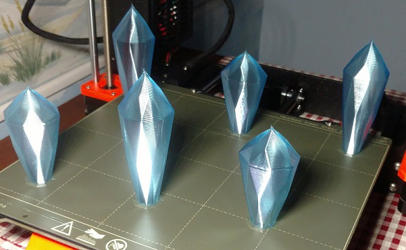
I promised you guys an actual print using Sequential printing with Spiral Vase enabled, so here it is- making Christmas Decorations. Parts here are 75 and 100mm tall, 34x34mm. I have full description and math used to calculate spacing, if anybody is interested. You might notice that the tops of these are fully closed, despite spiral vase mode. Just doing my part to further the game.
spiral vase mode is enabled. sequential print is enabled. Z clearance is 100. variable layer height from .4 to .6 on shorter gems (.6 on taller gems). 4mm brim.
RE: Spiral Vase + Sequential Printing + Multi Colour
Getting the positioning and print order does take some time. I managed to get 5 vases at once, but due to their size I had to let the rods actually hit an already printed one. Fortunately they are very flexible when printing with .4mm nozzle. The next step is printing with more than 1 colour. It would be nice to see those Christmas Decorations with colour change where the facets begin.
It is worth it!
Kenn
PS: any chance of getting the .3mf file?
Quality is the Journey, not the Destination. My limited prints->
RE: Spiral Vase + Sequential Printing (6 at a time)
I am interested in the math and process you used 😉
RE: Spiral Vase + Sequential Printing (6 at a time)
Sure thing. I've done better calculations since the last post I wrote on this, as I printed larger parts this time. To start, here's a screenshot of the settings to see spiral+sequential, and make sure to override the clearance tolerances.
**This entire next paragraph is not essential to be understood and can be skipped without consequence; it is, however, informationally accurate and has been included and intended for people who are simply curious to know some of the madness I was required to endure in order to arrive at a true understanding and be able to present real working calculations and procedures**
*Skip to the "picture of my settings" if you would like to skip my brain being spilled all over my keyboard in the following paragraph*
There are 3 tolerances you must know (X, Y, and Z), but only 2 input fields, and yet only one of them gets used by the slicing software to warn you in any helpful way (radius). What do I mean by that? During slicing/spacing you will get warnings regarding parts too close, and this ONLY is referring to the "radius" clearance, which will likely only apply to your X clearance (it could potentially refer to Y clearance but only if your part is much wider in X dimension forcing you to input the Y clearance instead; the radius clearance could theoretically refer to both X and Y clearances simultaneously if your part is the exact shape and orientation such that your X clearance (which is part width plus [distance from nozzle to edge of hotend fan]) is exactly equal to your Y clearance (which is depth of part+ [the distance of your nozzle to the edge of the part fan]) which is almost statistically impossible .....don't worry about that for now, just know that the warnings will likely only apply to your X-X clearance. "Radius clearance" is going to be the X tolerance only for this example (and always needs to be the smaller of the X clearance vs Y true clearances required, which is why it's purely up to your math skills for success because we're actually lying to the slicer in order for it to allow us to generate the g-code. The Z-height clearance needs to be equal to or higher than the tallest part even though this is also meaningless for the actual print as again we are lying to the slicer (I use 100mm here. In reality, these numbers are ignored by your printer for the entire print and are only used by the slicer to allow or prevent the gcode from being generated. Notice my part of 75mm doesn't meet the requirement of 100mm, because while printing a 75mm part the extruder will easily run into the 100mm parts that are already printed and yet changing the value to 75mm will result in the slicer warning me that my print is too tall and will fail, preventing me from generating g-code altogether. This clearance doesn't actually make any sense when applied to sequential printing. It is up to your math, print sequence, and extruder path if your parts are to be crushed or knocked over by the extruder and X-axis bars). I have 2 different part models here, X=37.31mm by Y=34.27mm by Z=75mm, and X=34.27mm by Y=34.27mm by Z=100mm. I leave the "Radius Clearance" at 45mm, even though I believe 30mm to be enough space to "actually clear" (but there's a good reason to have extra mm for X clearance....hotend fan... and then Y clearance for part fan we will also discuss later because it's a bit more involved).**

Ok so first off, I would like to thank you for expressing interest in this. I spent a few frustrated mornings doing various tests, and I believe to have the process worked out with all most of the relevant math and spatial relationships accounted for.
Print Order Sequence. Make sure to have the print order from Front Row, (followed by middle if you have one), and lastly Back Row. Also importantly, have each row print individually from Left to Right. 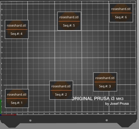
This is critical, as the hotend fan (on the "left" of the extruder while facing it) has a flat outer surface (as opposed to the part fan which is facing you and at an angle), while the other side (the right side as you face it) of the extruder has the super pinda and part fan (part fan isn't centered you will notice) which both extend farther to the right from the nozzle than the hotend fan on the left side, which is primarily why we want to print left to right. We will go over the math in a bit, but just keep in mind that the clearance is truly calculated from the nozzle to the potential contact point of the movable X-axis and extruder+wires/fans. We cannot do anything about the X axis being where it is, but we can choose to print Left to Right, which gives us more clearance on that side of the extruder as opposed to the side with the Super Pinda and such. So that is why we print L-to-R, now let's just look at why printing Front to Back, row by row.
Pretty simple logic here. Assuming you have spaced the first row correctly, the extruder will never again cross through this area of Y points. That means it will never interfere with parts printed on the front of the bed, even if they are maximum Z height. There are a few considerations to keep in mind with this (one of which I forgot to implement in this print which was useful for learning, and I now have additional math regarding the non-print row transition movement as a result). You will be spacing your second row according to the clearance required from the back of each part in your first row of printed parts to the part-fan at its front-most position according to the front-most edge of each part in this current row. Depending on the z-height of the "back of your part" in the first row (the side which might run into your extruder), you can use an exact minimum spacing or add extra to account for the angle of the part fan (as the fan requires more space as the part gets taller up unto the total height of the fan. A very short part will require less distance to clear as the fan is at an angle).
Something very important to remember, is that do not use minimum spacing unless you are absolutely positive you will have no stringing, as your fans will suck the stringing into themselves if you are extremely close.
So according to my physical measurements as best I could take, the distance from nozzle to edge of hotend-fan seems to be just about 1.25 inches, or 30mm ish. This is fine if you want the hotend fan smooching the side of each previously printed part, but for the sake of not trying to sand down one side of your part with the fan I leave the additional 15mm of default clearance. You can move it closer if you want to get another part or two to fit, especially if you have the seams somewhere that won't leave any potential stringing to get devoured (and if the parts you're printing are always nice and clean, you don't need to take this extra space precaution and can use 35 or 40mm or something you feel comfortable with). I've never done any "exact calibration test prints" to find exact minimum spacing, and maybe I will do this later today if I have time.....sorry it is not able to be included here. So does that mean we just print the parts 35mm spaced out? No, not unless your parts are 0mm wide. We must account for the part width. (To be technical, we derive this from the fact that we must add the distance from the center of the first part to its right-edge [which is 1/2 the part width since it's located on-center] and also add the distance of the "next part" center to its left-edge [again 1/2 the part width] ....and so we can just use the part width.) My parts are different widths, as I'm using 2 different sized crystal shapes alternating. They are 37.31mm and 34.27mm wide, so I divided both by 2 and rounded up to next mm to get 19mm and 18mm and add together to get 37mm. (If they were the same size, I could have just used the part width). I then add this to 45 (I use 45 instead of 35mm because I'm using .8 nozzle with fat layer height and swirlerizing the top of the gem so it actually fully closes despite spiral vase having 0 top layers, and as such I'm definitely going to account for stringing at the peak) which gives me 82mm. Add this to our starting X value of 30, and our next crystal will be printed at X=112. Add another 82 for the next part at X=194 (somehow I typed in 193 but it's all good). 
You may notice this picture for the second row doesn't match the Y positions from the earlier picture, and that's only because I had the extra space so I decided to space out the second row +30Y and +15X from the first row. Also, because I forgot GOLDEN RULE #2 (always have the tallest parts in the RIGHT COLUMN) I ended with the shorter crystal in the right column of the first row, and when the extruder went from the front row to the back row, it ALMOST hit crystal #2 positioned at 112,45. Because our back row had been spaced more (I translated the entire back row by +30 Y simply because I had the space as mentioned before), the extruder path to crystal #4 from #3 now was such that the part fan just barely missed touching crystal #2. Had I correctly put the tallest part on the outside (right column), the extruder would have cleared the height of all the parts and would have had no ability to knock anything over during this transition.
Ok moving on.... Looking at the Front Row of parts, you might notice that I offset the middle and right columns by 15Y each. This is because the X-axis bars require clearance. As you print your front row, your X axis bars must have clearance in order that they do not knock over the part you just finished printing in that row. This is measured from the nozzle to the X-axis bars. It's kinda hard to measure but it looks to be somewhere between 25mm and 30mmish. These parts are deeper in the Y dimension than this value (they are 34.27mm), and this means that when printing part #2 the X-axis is going to run into the part #1. Both of my crystals are 34.27 in Y dimension, and so I am going to add +15 Y units offset so it has a few extra mm beyond what is necessary. If your parts are under 25mm in the Y dimension, they can be printed along the row with the same Y value without any issues. Because I used a +15mm offset for each of the subsequent front row parts, this offset will carry over to our back row. How to calculate space required for the back row from the front row? Measuring the distance from the nozzle to the front of the part fan gives a nice 2.5 inches, or 62.5mm, which we will add to the part Y-depth, (and add this to the Y-coordinate location of first row to get the value for second row). This number of 62.5mm is at full height of part fan, and since our parts are tall enough I will be using this figure. If my parts were very short, I could use 30-60mm depending on how short and how adventurous I am and if I have spare part fans lying around. Just like with the X clearance calculations, we are going to take the part Y-depth dimension and add it to the nozzle-fan distance value, which is to say 35mm (rounding up from 34.27) + 62.5mm to equal 97.5mm clearance needed. Add this to our initial Y-coordinate value of 30, and our second row will start at Y=127.5 We now finish the coordinates for the rest of the row. Easy math now, as we know subsequent columns will receive X= +82mm (and offset +15Y). And now you're done.........as long as you didn't forget to have the rightmost column be your tallest parts. Here is where I simply had additional room, so I translated the back row by +30Y and because my peak of the crystals was sure to have extra stringing I also added space of additional +15X between them in the back row to ensure the part fan didn't snack on the stringing (by adding +15X to the middle and +30X to the rightmost part)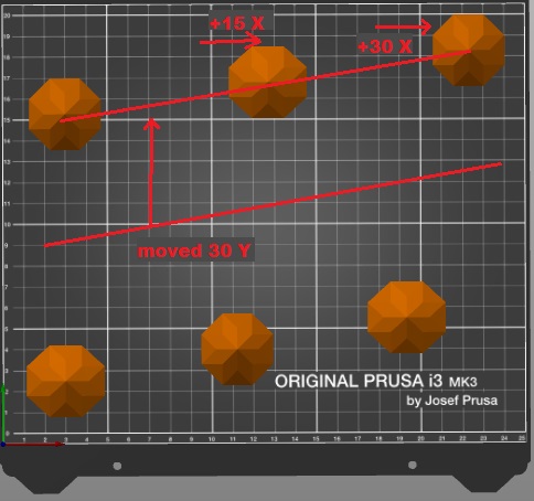
Again, I did this only because I had extra space, and it was not required. I did NOT shift the first row, simply to test and prove that the X-clearance spacing was adequate, and the extra space in the back row was unnecessary (but it felt nice). The print succeeded wonderfully, and hopefully this is helpful for anyone wishing to calculate more precise math. Parts can be super tricky to space depending on the geometry, especially when they do not have flat transitions to upper layers and angled outer sections. If I missed something or explained something incorrectly, please let me know so I can address this. I proofread this in order to fix anything I typed wrong, but I still might have missed something.

Posted by: @terry-sherman
I am interested in the math and process you used 😉
RE: Spiral Vase + Sequential Printing (6 at a time)
I'm going to print 100 parts with spiral vase and sequential printing, JUST TO PROVE IT CAN WORK LOL.
RE: Spiral Vase + Sequential Printing (6 at a time)
this can be accounted for, and if you even....omg.....omg....omg....omg....omg.....I just realized magical.
You can ignore all clearances by having your parts literally right up against each other and PAUSE the print between parts.....let it cool for a couple seconds.....remove previous part....unpause......wahhhhh i dont have time for this today but this sounds so insanely interesting....
But what I was gonna say, i address the X-bars in my post and you can account for it with the math
Was your request for the .3mf file directed towards me? If so, sure thing.
Getting the positioning and print order does take some time. I managed to get 5 vases at once, but due to their size I had to let the rods actually hit an already printed one. Fortunately they are very flexible when printing with .4mm nozzle. The next step is printing with more than 1 colour. It would be nice to see those Christmas Decorations with colour change where the facets begin.
It is worth it!
Kenn
PS: any chance of getting the .3mf file?
RE: Spiral Vase + Sequential Printing (6 at a time)
@eggkthganegkthkg
"Was your request for the .3mf file directed towards me? If so, sure thing.
If you don't mind.
Since it is a PoC, you can PM me with it, or post it here.
You can ignore all clearances by having your parts literally right up against each other and PAUSE the print between parts.....let it cool for a couple seconds.....remove previous part....unpause......wahhhhh i dont have time for this today but this sounds so insanely interesting....
Or if you are really insane, you could use the rods/carriage to auto eject the finished one(s). Once when I was doing some sequential print testing I accidentally went through a finished vase (with 100mm diameter base) with the rods and it went flying across the room. The printer didn't even notice and carried on. NOOBs - do not try this!!!! The OP is testing the limits of the software and hardware and is prepared to handle surprises.
Quality is the Journey, not the Destination. My limited prints->
How did you get spiral vase to close at the top?
Was there something special? Or is it just don't try and have a flat top?
Where did you specify the order to print sequentially?
I'm not seeing a way to say print all of the left column first ? That doesn't even seem right - doing the all on left side first will knock over all of the finished prints when it moves to the middle column. So it must be front row first, second row next, etc.
Did the auto-arrange pick the positions? Or did you have to manually place each item. How did you get sequential to not complain when there are more than one item on the screen. Some things still seem to be missing from the recipe
RE:
I'm not printing the left column first. I'm printing the front row first, from left to right. Next row back, from left to right. I believe I included a screenshot showing the printing sequence
I manually picked the order.
I didn't go into all the details about setting it up, I apologize, I wasn't expecting such a positive response.
You must use "expert mode" and override the clearance tolerances (radius and height. Height must be at least as tall as your tallest piece and radius is from nozzle tip to nearest part). The warnings will never display if you use the right values, but this doesn't mean your print is positioned correctly as my post explains, you are responsible for calculate the actual positions. The warnings will NOT help you in any way, except for X clearances.
I wasn't able to edit the original post, and all of my calculations and such are in a follow-up comment I posted. Maybe someone can edit my original post to include that?
I'm not seeing a way to say print all of the left column first ? That doesn't even seem right - doing the all on left side first will knock over all of the finished prints when it moves to the middle column. So it must be front row first, second row next, etc.
Did the auto-arrange pick the positions? Or did you have to manually place each item. How did you get sequential to not complain when there are more than one item on the screen. Some things still seem to be missing from the recipe
RE: Spiral Vase + Sequential Printing (6 at a time)
I did not do anything special to get the top to close actually. I believe I was able to achieve this due to a combination of nozzle size, layer height and extrusion width, and I did use a height range modification to change layer height and also the overlap for the upper section of the shorter crystal (did not do this for the taller one because the angle was steep enough already). So basically, it "still didn't print the very top" of it, but because the print comes to a fine pointed tip, I believe there was enough height in the .4 layers below the very top that it still closed completely. Think of it as a pyramid vs a cube- the pyramid has a top layer thats very very tiny, and the cube has a top layer equal to the bottom layer. If you shave off the top layer of the pyramid, you have only a tiny hole to fill. In this case, there was no hole at all. Pretty sweet. Im not sure if you could get something to work with a flatter top, but probably if you modified these settings a bit, slowed it down, and....woah I actually think you might be able to abuse the overlap with these settings tweaked to get an 85-near90 degree plane. You guys are giving me more things to mess around with than time available!
Was there something special? Or is it just don't try and have a flat top?
RE: Spiral Vase + Sequential Printing (6 at a time)
I'm not printing the left column first. I'm printing the front row first, from left to right. Next row back, from left to right. I believe I included a screenshot showing the printing sequence
I manually picked the order.
I didn't go into all the details about setting it up, I apologize, I wasn't expecting such a positive response.
You must use "expert mode" and override the clearance tolerances (radius and height. Height must be at least as tall as your tallest piece and radius is from nozzle tip to nearest part). The warnings will never display if you use the right values, but this doesn't mean your print is positioned correctly as my post explains, you are responsible for calculate the actual positions. The warnings will NOT help you in any way, except for X clearances.
I wasn't able to edit the original post, and all of my calculations and such are in a follow-up comment I posted. Maybe someone can edit my original post to include that?
I'm not seeing a way to say print all of the left column first ? That doesn't even seem right - doing the all on left side first will knock over all of the finished prints when it moves to the middle column. So it must be front row first, second row next, etc.
Did the auto-arrange pick the positions? Or did you have to manually place each item. How did you get sequential to not complain when there are more than one item on the screen. Some things still seem to be missing from the recipe
you have to manually choose the print order. sorry i'm so late on this response. if you dont already know, it's in the menu of "view" and "show labels". ~ hope this helps